background image

Instruction Manual

16

Auto Scan

In this mode, the Console automatically switches from one powered computer to 

the next, sequentially in a fixed interval. During Auto Scan mode, the OSD displays 

the name of the selected computer. When Auto Scan detects any keyboard or mouse 

activity, it suspends the scanning until activity stops; it then resumes with the next 

computer in sequence.  To abort Auto Scan mode, press the left <CTRL> twice, or, press 

any front button. Scan Type and Scan Rate set the scan pattern. Scan Type (<F4>:More\

Scan Type) determines if scanned computers must also be eye mark selected. Scan 

Rate (<F4>:More\Scan Rate) sets the display interval when a computer is selected 

before selecting the next one.

Manual Scan

Scan through power-on computers one by one by keyboard control.Scan Type 

(<F4>:More\Scan Type) determines if scanned computers must also be eye mark 

selected. Press the up arrow key to select the previous computer and the down arrow 

key to select the next  computer. Press any other key to abort Manual Scan mode.

Audio Stick

An  optional  multimedia  module  can  be  linked  to  the  back  of  each  KVM  Module  for 

selecting microphone and stereo speaker signals. There are two options for Audio Stick: 

On and Off. When set to On, audio selection follows computer selection.
When  set  to  Off,  audio  selection  stops  following  computer  selection. 

It  is  useful  if  you  want  to  listen  to  a  particular  computer’s  audio  signal 

while  operating  other  computers.  The  non-volatile  memory  stores  the  

Audio Stick setting.

Summary of Contents for DuraView RACKCONS1708

Page 1: ... com ES Guía del usuario es startech com IT Guida per l uso it startech com NL Gebruiksaanwijzing nl startech com PT Guia do usuário pt startech com RACKCONS1708 RACKCONS1716 RACKCONS1908 RACKCONS1916 RKCONS1708GB RKCONS1716GB RKCONS1908GB RKCONS1916GB RKCONS1708EU RKCONS1916EU 1U 17 19 Rackmount LCD Console with 8 16 Port KVM Switch actual product may vary from photos ...

Page 2: ...receiving antenna Increase the separation between the equipment and receiver Connect the equipment into an outlet on a circuit different from that to which the receiver is connected Consult the dealer or an experienced radio TV technician for help Use ofTrademarks RegisteredTrademarks and other Protected Names and Symbols This manual may make reference to trademarks registered trademarks and other...

Page 3: ...tents Introduction 1 Packaging Contents 1 Installation and Usage 2 Hardware Guide 2 Connecting the Console Module 6 Connecting computers to the module 8 Module Operation 13 Specifications 21 Technical Support 22 Warranty Information 22 ...

Page 4: ...e with 17 monitor with a 16 port KVM switch allowing you to manage multiple computers using an integrated keyboard mouse and TFT screen that slides into a compact 1U of rack space when not in use Packaging Contents 1x 1U LCD Rack Console Drawer 1x 1U Multi Platform KVM Switch 1x Mounting Rails Set 1x Mounting Brackets 1x Power Adapter ...

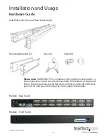
Page 5: ...Module Rear Panel Module Front Panel Hardware Guide Please note RACKCONS1716 is comprised of two distinct components a Rackmountable Console and a Rackmountable KVM Module as illustrated below The two devices are attached via a Centronics connector on the Rear panel of the Console and similarly the front panel of the Module ...

Page 6: ...nual 3 Console Front View open Mounting the Console 1 Loosen the rear screws pre installed in side rails and adjust the length of the rear bracket to fit the depth of your cabinet 2 Install the rail into the cabinet ...

Page 7: ...by the Console and the female Centronics connector provided by the Module Ensure the connection is secure and that the module is firmly seated within the Console side rails 6 Gently but firmly insert the Console with Module attached into the left and right rails 7 Unlock the console and pull the left and right rail lock switches towards you simultaneously and hold them in this position while pushi...

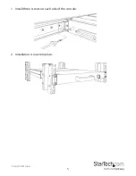
Page 8: ...Instruction Manual 5 1 Install three screws on each side of the console 2 Installation is now complete ...

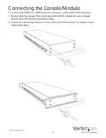
Page 9: ...sole Module to a computer perform the following steps 1 Remove the four screws from both sides of the KVM console Be sure to retain these screws for the next installation step 2 Attach the mounting brackets to both sides of the KVM console using the screws removed in step 1 ...

Page 10: ...Instruction Manual 7 3 From the rear of the cabinet slide the KVM console onto the mounting rails 4 Install one screw on each side of the console as depicted below ...

Page 11: ... Cascade Configuration You can connect a second level of KVMs to one or more of your Master KVM console s PC ports The KVM switches connected to the Master console are known as Slaves Once connected the KVM switches will automatically configure themselves as either Masters or Slaves You can only connect an equal or smaller KVM to the Master KVM For example a 16 port Master KVM switch can have both...

Page 12: ...ue In most cases you can adjust these settings using a program or utility provided by the manufacturer of the video card Most video cards use the Windows Display Properties control panel to configure the display To open the Windows Display Properties click the right mouse button in a blank area of the Windows desktop and then select Properties The Settings tab usually lets you change the Color Pal...

Page 13: ...ing to the console have been turned off To prevent damage to your installation due to ground potential difference make sure that all of the devices being installed are properly grounded Once all peripherals have been connected please power them on Panel controls and OSD functions The following controls are located on the console monitor Auto tune Press the Auto tune button The panel will adjust th...

Page 14: ...nd Up buttons to adjust the brightness of the display 5 Press the Menu button to save your selection Contrast 1 Press the Menu button 2 Use the Down and Up buttons to scroll to Contrast 3 Press the Menu button to enter 4 Use the Down and Up buttons to adjust the contrast of the display 5 Press the Menu button to save your selection Color 1 Press the Menu button 2 Use the Down and Up button to scro...

Page 15: ...Menu button to select which will launch the following screen 4 Use the Down and Up buttons to scroll and highlight the preferred language 5 Press the Menu button to save your selection Icon Description 9300 K To set CIE coordinates at 9300 K color 7500 K To set CIE coordinates at 7500 K color 6500 K To set CIE coordinates at 6500 K color User To set user defined CIE Auto color To auto adjust color...

Page 16: ...tch press and hold front panel buttons 1 and 2 simultaneously The Auto Scan function automatically scrolls through your connected computers Press and hold front panel buttons 7 and 8 simultaneously to enter Auto Scan mode By hitting the left CTRL key twice within two seconds you may see the Hotkey Menu if it is enabled as an OSD option Or by hitting the left CTRL key three times within two seconds...

Page 17: ...he right of a name indicates that the computer is selected to be monitored in Scan mode In OSD this mark can be switched on or off by function key F2 Press the ESCAPE key to exit OSD and to return to the selected computer the computer name is also shown on the screen Editing Computer Name Assignments Function key F1 To edit the name entry of a computer or a Slave first use the up and down arrow ke...

Page 18: ...ed device temporarily simply highlight it and press ENTER The OSD will prompt for the password After entering the correct password you are allowed to use the device This device is automatically re locked once you switch to another one During Scan mode OSD skips the security enabled device Please Note Only one device a computer or a Slave can be locked by this function at a time Please note If you ...

Page 19: ... a computer is selected before selecting the next one Manual Scan Scan through power on computers one by one by keyboard control Scan Type F4 More Scan Type determines if scanned computers must also be eye mark selected Press the up arrow key to select the previous computer and the down arrow key to select the next computer Press any other key to abort Manual Scan mode Audio Stick An optional mult...

Page 20: ...onds the Hotkey Menu appears displaying a list of hot key commands if the option is On The Hotkey Menu can be turned Off if you prefer not to see it when the left CTRL key is hit twice The non volatile memory stores the Hotkey Menu setting CH Display Auto Off After you select a computer the port number and name of the computer will appear on the screen for 3 seconds then disappear automatically Wh...

Page 21: ...key Menu every time the left CTRL key is pressed twice L CTRL is the CTRL key located at the left side of the keyboard 1 8 A H are the number keys 1 8 at the upper row of the keyboard and character keys A H case insensitive Do not use the keypad at the right of the keyboard To select a computer by hot key command you must know its port number which is determined by the KVM Module connection For a ...

Page 22: ...ter the port number on the slave KVM where the PC is connected Ex Left Ctrl Left Ctrl 3 1 would select the computer connected to port 1 of the slave KVM that is connected to port 3 on the console Start Auto scan Left Ctrl Left Ctrl F1 Automatically scans through powered on computers Whenkeyboardormouseactivityissensed auto scanpausesuntilactivitystops End Auto scan Left Ctrl Left Ctrl Exits auto s...

Page 23: ...em The console will generate one to four beeps corresponding to 10 15 20 and 30 characters sec respectively to signify the typematic rate Change Configuration while Running A device a computer or a KVM switch at any PC x port can be changed at anytime after initial power up If you change any one of the PC 1 to PC 8 ports connection from a computer to a Slave or vice versa or replace the devices of...

Page 24: ... output Inactive 1 x PS 2 Keyboard 6 pin Mini Din Female 1 x PS 2 Mouse 6 pin Mini Din Female Panel Type Active Matrix TFT LCD Resolution Capabilities 1280 x 1024 XGA Pixel Pitch Supports 0 264mm x 0 264mm Supports 0 098mm x 0 294mm Back Light Four lamps Viewing Angle Right Left view 60 70 Typ Up Down View 45 60 Typ Right Left view 140 Typ Up Down View 140 Typ Contrast Ratio 450 1 500 1 Brightness...

Page 25: ...ssian Sync 45 80KHz Power Source 100 240 VAC input Power Adapter 12VDC 4A Power Consumption 25W 19 05W for Panel 25W 21 05W for Panel Operating Temperature 0 C 50 C 32 F 122 F Storage Temperature 20 C 60 C 4 F 140 F Humidity 10 90 RH Min Max Mounting Depth 504mm 1000mm 19 84in 39 37in 554mm 1000mm 21 8in 39 37in Dimensions 440 x 470 x 44mm 490 x 470 x 44mm Net Weight 11 75kg 12 75kg Chassis Constr...

Page 26: ...e returned for repair or replacement with equivalent products at our discretion The warranty covers parts and labor costs only StarTech com does not warrant its products from defects or damages arising from misuse abuse alteration or normal wear and tear Limitation of Liability In no event shall the liability of StarTech com Ltd and StarTech com USA LLP or their officers directors employees or age...

Page 27: ...rts and we quickly deliver them wherever they need to go Just talk to one of our tech advisors or visit our website You ll be connected to the products you need in no time Visit www startech com for complete information on all StarTech com products and to access exclusive resources and time saving tools StarTech com is an ISO 9001 Registered manufacturer of connectivity and technology parts StarTe...

Reviews: