background image

12  PKG08812-QRGDFC

ENGLISH

USING TOLERANCE LIMITS

Use tolerances to setup "pass" and "fail" 
measurements. You may specify a Limit 1 and a 
Limit 2 to create a tolerance band. Measured results 
that equal or fall within the range created by the two 
limits are considered "pass" results. If the measured 
result falls outside the band created by the two 
Limits, the result is considered a "fail" result. A "fail" 
results displays in RED.

Press

q

Move to TOLERANCE

Press

u

Select ENABLE

Press

q

Move down to LIMITS

Press

q

Move down to LIMIT 1

Press

u

Select Limit 1 value using 

qp

Press

t

Move out of Limit 1

Press

q

Move down to LIMIT 1

Press

u

Select Limit 2 value using 

qp

Press

t

Move out of LIMIT 2

Press

t

Move out of TOLERANCE

SAVING RESULTS

The DFC feature an internal memory for saving 
results for the purpose of calculating and displaying 
statistics. You may save up to 99 individual results 
in memory. 
To save results to memory, you must configure 
a softkey with the SAVE function. Press the SAVE 
softkey to save the displayed results to memory. 
Results saved to memory MUST be of the same type. 
You cannot have mixed type results. For example, you 
cannot save tension results with COF results. Results 
MUST be of the same type.
Results obtained using the TESTS feature are saved in 
pairs. For each test, there is a Load and Distance result 
(L-D). You cannot save results from different types of 
tests. For example, you cannot save results from a 
Load Limit test with results from a Break Limit test. 
Each load-distance pair of results must have come 
from the same test type: Load, Distance or Break.

lbf

5.71

5.66

4

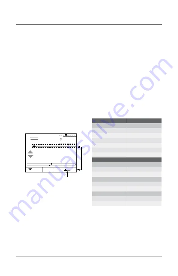
Shown: Peak Tension view with Tolerance result

Peak Tension Mode Indicator

Real Time value

RESULT TYPE

MEMORY TYPE

MODES

Real Time

Real Time

Tension Peak

Tension Peak

Compression Peak

Compression Peak

Average

Average

Static COF

Static COF

Kinetic COF

Kinetic COF

TESTS

LOAD LIMIT TEST

Distance @ Limit

Distance @ Limit

Load Limit

Load Limit

DISTANCE LIMIT TEST

Load @ Limit

Load @ Limit

Distance Limit

Distance Limit

BREAK LIMIT TEST

Load Max (Peak Load)

Load Max (Peak Load)

Distance @ Load Max

Distance @ Load Max

Summary of Contents for DFC-10

Page 1: ...Trust Is In The Name Quick Reference Guide PKG08812 QRGDFC ...

Page 2: ... EL INSTRUMENTO LEA ATENTAMENTE ESTE MANUAL LIRE CE MANUEL AVANT D UTILISER L INSTRUMENT LEIA ATENTAMENTE ESTE MANUAL ANTES DE UTILIZAR O INSTRUMENTO 使用仪器前请阅读本操作手册 DIESES HANDBUCH VOR DER VERWENDUNG DES MESSGERÄTS LESEN LEGGERE ATTENTAMENTE QUESTO MANUALE PRIMA DI UTILIZZARE QUESTO STRUMENTO ...

Page 3: ...PKG08812 QRGDFC 3 DFC DIGITAL FORCE CONTROLLER QUICK REFERENCE GUIDE ...

Page 4: ...n 6 Keypad and Navigation 8 On Off Menu Key 8 Zero Key 8 Softkey 1 8 Softkey 2 8 Controller Display Formats 11 Using Tolerance Limits 12 Saving Results 12 Clear Results from Memory 13 View Statistics 13 Export Results 13 Gage Setup 13 Charging Battery 14 ...

Page 5: ... IS A STARRETT QUICK REFERENCE GUIDE FOR THE DFG DIGITAL FORCE CONTROLLER ALL SPECIFICATIONS IN THIS DOCUMENT ARE CORRECT AT TIME OF PRODUCTION AND ARE SUBJECT TO CHANGE PLEASE CONTACT STARRETT FOR FURTHER INFORMATION PKG08812 QRGDFC 5 ...

Page 6: ...0 Display Resolution 10 000 1 Safe Overload Full Scale 200 Maximum Tare 10 COMMUNICATIONS Bluetooth Yes USB 2 0 Yes RS 232 Yes Digital I O 2 channels Memory saved results max 99 OPERATING MODE Machine Control1 Yes Real Time Yes Peak Compression Yes Peak Tension Yes Load Limit Yes Break Limit Yes Load Average Yes Load Time Average Yes Cyclic Count Max 99 999 Cyclic Duration Max 27 Hrs Hold Duration...

Page 7: ...0 10 20 320 9 000 0 008 0 20 M6 x 1 6H SPK FG S DFC 50 250 25 50 800 23 000 0 015 0 39 M6 x 1 6H SPK FG S DFC 100 500 50 110 1 600 45 000 0 024 0 60 M6 x 1 6H SPK FG S DFC 200 1 000 100 225 0 021 0 54 M6 x 1 6H SPK FG M DFC 500 2 500 250 550 0 028 0 70 M10 x 1 5 5H SPK FG L NOTES Load measurement accuracy is 0 1 of load cell capacity Display resolution is 10 000 1 3 30 83 8 Thread 0 91 23 0 1 63 4...

Page 8: ... assign how Softkey 1 performs For example you can assign a SAVE function to the key When pressed the measured values are saved to memory SOFTKEY 2 This is the right arrow key It is used to move in to a setup when in the Setup Menu u Like the Softkey 1 it also may be mapped to a specific function For example you can assign a MODE function to the key Pressing the key can change the operating modes ...

Page 9: ...cell Compression Direction Peak Max Compression Real Time Mode Indicator Shown Peak Tension view Peak Tension Mode Indicator Real Time value Tensile Direction Peak Max Tension Shown Peak Tension view with Tolerance result Peak Tension Mode Indicator Real Time value Shown Peak Compression view Peak Compression Mode Indicator Real Time value Compression Direction Peak Max Compression ...

Page 10: ... of measure for displayed results Battery Status Shows remaining battery life Shows functions mapped to softkeys 1 and 2 Menu function is always center key Shown Display in Classic mode Shown Display in Controller mode used with FMM Test Frame Shows Load measured by load cell Shows Distance measured by encoder on the FMM Test Frame Shows Load unit of measure Shows Distance unit of measure Load Bar...

Page 11: ... universal interface for the system and will be used to setup the force gage and the tester The DFC force gage will display load information as measured by the load cell The DFC force gage will display distance information as measured by the FMM digital force tester Shown Load Limit Test results Shown Distance Limit Test results Shown Break Limit Test results L 16 55 100 00N 5 N mm 16 64 D L 27 45...

Page 12: ...key with the SAVE function Press the SAVE softkey to save the displayed results to memory Results saved to memory MUST be of the same type You cannot have mixed type results For example you cannot save tension results with COF results Results MUST be of the same type Results obtained using the TESTS feature are saved in pairs For each test there is a Load and Distance result L D You cannot save re...

Page 13: ...etup Backlight Brightness Press u to setup Flip orientation required for TESTS feature Press u to setup Radix Press t to exit Display setup FILTERS Press q for Filters Press u to specify filter rate Press t to exit Filter setup SETTINGS Press p for Menu Press q for Settings select Settings Type TESTS Press p for Menu Press q for Tests Press u to Enable Tests Press q to your Test Method Press u to ...

Page 14: ...vice USB 2 0 Charge DFC Battery Upload firmware and new features to DFC from a PC Export data to a printer Export data to a PC RS 232 Communicate with a serial printer Communicate with a serial external computer or hard drive Control Controls the crosshead direction and velocity the FMM from the DFC gage Gage Setup Menu Structure RS 232 USB 2 0 MODES UNITS MEMORY TESTS TOLERANCE KEYS SETTINGS Real...

Page 15: ... COM ATHOL MA USA 01331 1915 EUROPE ASIA WWW STARRETT CO UK JEDBURGH SCOTLAND TD8 6LR SOUTH CENTRAL AMERICA WWW STARRETT COM BR 13306 900 ITU SP BRASIL CNPJ 56 994 700 0001 01 CHINA WWW STARRETT COM CN USER MANUALS AVAILABLE ONLINE AT STARRETT COM ...

Page 16: ...Starrett com ...

Reviews: