background image

Technical Primer - Aurora

Contents

1 Copyright and Disclaimer

5

1.1 Disclaimer . . . . . . . . . . . . . . . . . . . . . . . . . . . . . . . . . . . . . . . . . . . . . . . . .

5

1.2 Copyright . . . . . . . . . . . . . . . . . . . . . . . . . . . . . . . . . . . . . . . . . . . . . . . . .

5

1.3 Warranty . . . . . . . . . . . . . . . . . . . . . . . . . . . . . . . . . . . . . . . . . . . . . . . . . .

5

2 Safety and Usage instructions

6

2.1 General safety . . . . . . . . . . . . . . . . . . . . . . . . . . . . . . . . . . . . . . . . . . . . . .

6

2.2 Summary of safety symbols on the equipment . . . . . . . . . . . . . . . . . . . . . . . . . .

6

3 Technical Data about the Product

7

3.1 Technical Specifications . . . . . . . . . . . . . . . . . . . . . . . . . . . . . . . . . . . . . . . .

7

3.1.1 Mains Supply Parameters . . . . . . . . . . . . . . . . . . . . . . . . . . . . . . . . . . .

7

3.1.2 Output of the Charger / Connecting to the EV . . . . . . . . . . . . . . . . . . . . . .

8

3.1.3 Protection features and integrated components for Safety . . . . . . . . . . . . . . .

8

3.1.4 Charging and access . . . . . . . . . . . . . . . . . . . . . . . . . . . . . . . . . . . . . .

8

3.1.5 Operating conditions and Physical aspects . . . . . . . . . . . . . . . . . . . . . . . .

9

3.1.6 Accesories . . . . . . . . . . . . . . . . . . . . . . . . . . . . . . . . . . . . . . . . . . . . .

9

3.2 Appearance Overview - Case B type . . . . . . . . . . . . . . . . . . . . . . . . . . . . . . . . . 10

3.3 Appearance Overview - Case C type . . . . . . . . . . . . . . . . . . . . . . . . . . . . . . . . . 10

3.4 LED status Indications . . . . . . . . . . . . . . . . . . . . . . . . . . . . . . . . . . . . . . . . . 11

4 Installing and Connecting the Charger

12

4.1 Package content . . . . . . . . . . . . . . . . . . . . . . . . . . . . . . . . . . . . . . . . . . . . . 12

4.2 Installations site requirements . . . . . . . . . . . . . . . . . . . . . . . . . . . . . . . . . . . . 12

4.3 Tools and equipment required to install the Aurora . . . . . . . . . . . . . . . . . . . . . . . 13

4.4 Wall Mounting . . . . . . . . . . . . . . . . . . . . . . . . . . . . . . . . . . . . . . . . . . . . . . 13

4.4.1 Wall Mounted Installation Steps . . . . . . . . . . . . . . . . . . . . . . . . . . . . . . . 13

4.5 Cement Foundation requirements for mounting the metal pedestal . . . . . . . . . . . . . 15

4.5.1 Installation distance of parking space for column type single pile or double pile

installation . . . . . . . . . . . . . . . . . . . . . . . . . . . . . . . . . . . . . . . . . . . . 15

4.5.2 Coulmn Installation steps . . . . . . . . . . . . . . . . . . . . . . . . . . . . . . . . . . . 15

5 Commissioning the charging pile

17

5.1 Safety instructions before commissioning . . . . . . . . . . . . . . . . . . . . . . . . . . . . . 17

5.2 Wiring steps before commissioning . . . . . . . . . . . . . . . . . . . . . . . . . . . . . . . . . 17

5.3 Debugging . . . . . . . . . . . . . . . . . . . . . . . . . . . . . . . . . . . . . . . . . . . . . . . . . 18

5.3.1 Establishing connection . . . . . . . . . . . . . . . . . . . . . . . . . . . . . . . . . . . . 18

5.3.2 Using third party back-end . . . . . . . . . . . . . . . . . . . . . . . . . . . . . . . . . . 18

6 Instructions for Charging

19

6.1 Summary of charging operation . . . . . . . . . . . . . . . . . . . . . . . . . . . . . . . . . . . 19

6.1.1 RFID-charging station with user authorization . . . . . . . . . . . . . . . . . . . . . 19

6.1.2 Swiping card to start and stop charging . . . . . . . . . . . . . . . . . . . . . . . . . . 19

6.1.3 Scanning QR code for user authorization . . . . . . . . . . . . . . . . . . . . . . . . . 20

6.1.4 Scanning QR Code to start and stop charging . . . . . . . . . . . . . . . . . . . . . . 20

6.2 Indicator Description . . . . . . . . . . . . . . . . . . . . . . . . . . . . . . . . . . . . . . . . . . 21

7 Maintenance

22

7.1 Routine Maintenance . . . . . . . . . . . . . . . . . . . . . . . . . . . . . . . . . . . . . . . . . . 22

7.2 Charging control logic . . . . . . . . . . . . . . . . . . . . . . . . . . . . . . . . . . . . . . . . . 22

7.2.1 Logic of Building-blocks . . . . . . . . . . . . . . . . . . . . . . . . . . . . . . . . . . . 22

7.2.2 Typical control pilot circuit . . . . . . . . . . . . . . . . . . . . . . . . . . . . . . . . . . 23

8 Common troubleshooting examples

24

8.1 The Charger cannot be powered ON . . . . . . . . . . . . . . . . . . . . . . . . . . . . . . . . . 24

8.2 The charger is connected to the vehicle but charging doesn’t get recognized by the EV . 25

8.3 Input Overvoltage/Undervoltage is observed . . . . . . . . . . . . . . . . . . . . . . . . . . . 26

8.4 Earth fault observed . . . . . . . . . . . . . . . . . . . . . . . . . . . . . . . . . . . . . . . . . . 26

8.5 Not fully charged, report that the battery is full or the connection is unsuccessful . . . 27

Wanbang Digital Energy Co.Ltd

4

Summary of Contents for Aurora 11kW

Page 1: ...Technical Primer Aurora 11kW ...

Page 2: ...2 Wanbang Digital Energy Co Ltd Installation Manual ...

Page 3: ...ion process and to fully utilize all advanced features of your new system we advise you to read this manual carefully Properly store this manual for future usage We have invested a great amount of care to provide you with a complete and comprehensible manual As we continue to modify and further improve its contents please refer to the following link to download the most recent version http www sta...

Page 4: ...istance of parking space for column type single pile or double pile installation 15 4 5 2 Coulmn Installation steps 15 5 Commissioning the charging pile 17 5 1 Safety instructions before commissioning 17 5 2 Wiring steps before commissioning 17 5 3 Debugging 18 5 3 1 Establishing connection 18 5 3 2 Using third party back end 18 6 Instructions for Charging 19 6 1 Summary of charging operation 19 6...

Page 5: ...duct Customization is the main cause Contact your dealer for more information on Customization versus the default product 1 2 Copyright All rights reserved The disclosure duplication distribution and editing of this document or utilization and communication of the content are not permitted unless authorized in writing All rights including rights created by patent grant or registration of a utility...

Page 6: ...rsonal injuries or death caused by operation steps practice or incorrect implementation The operation after the warning sign can only be performed when the conditions are fully understood and satisfied Caution which indicates a hazard Pay attention to the damaged or destroyed product caused by the operation steps experiments or incorrect execution Only after fully understanding and satisfying the ...

Page 7: ...has the following protection feature Lightning protection Overload protection Leakage protection Over voltage protection Under voltage protection PE Protective Earth detection 3 1 Technical Specifications 3 1 1 Mains Supply Parameters Recommended cable diameters at the input Minimum UL AWM1015 9AWG outside diameter 13 mm 15 mm Nominal line input voltage 400V AC 10 Limits of input power 3 phase 16 ...

Page 8: ...ous activation Overcurrent protection Integrated in firmware shutdown at 110 after 100 seconds 125 Immediately Attention Your installation must comply with the standards and regulations of the region where it is located The tables are advisory and based on proper practical functioning of the charging stations provided that all prerequisites are satisfied 3 1 4 Charging and access Controllers Centr...

Page 9: ... post AJGSMP1970 Dimensions H x W x D 1650 x 320 x 120 mm Material SUS304 stainless steel Electrostatic powder spraying Outdoor polyester powder coating High weather resistance PC material Color Silver and Black Packaging H x W x D 409 x 282 x 148 mm Weight Approx 5 6 k g Additional RFID card StarCharge card Notice If temperature exceeds the maximum values the charging station will automatically a...

Page 10: ...ector socket E QR code location for authentication 3 3 Appearance Overview Case C type Figure 2 Aurora Case C type A Cable winding trough B Emergency stop button To stop ongoing session immediately C Charge connector unlock button D Swiping card area to Start Stop charging E LED Status Indicator F Position of the charging connector and cable winding bracket G QR code location for authentication Wa...

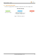
Page 11: ...Technical Primer Aurora 3 4 LED status Indications The Aurora is equipped with a color LEDs to visualize the status of the charging station Figure 3 LED status indicator Wanbang Digital Energy Co Ltd 11 ...

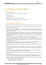
Page 12: ...ed and solid underground The wall mounted charging pile must be connected to the wall at least two points The wall should withstand the weight of the charging pile and its accessories The wall and internal lines should not be too close The indoor installation protection level should be at least IP32 and the outdoor IP54 It is recommended that the charger be installed in an environment with a sunsh...

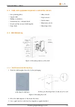
Page 13: ...Tool hammer Expansion screws Mounting screws 4 4 Wall Mounting Figure 4 Mounting Aurora on the wall 4 4 1 Wall Mounted Installation Steps 1 Take the drill template from the carton packaging a Marking the drill holes b Fixing the Mounting Block attachment on the wall Figure 5 Readying the wall 2 Place the drill template at the desired location 3 Use a spirit level to verify that the template is app...

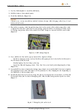
Page 14: ...it for the wall to open 4 holes with a depth of 70mm Install an expansion tube and use two M6 self tapping screws to fasten the wall mount to the two holes under the wall Directly tighten the two holes on the top Insert two M6 self tapping screws Note that the screw head protruding height is 7mm Figure 5b 9 Use six M4 12 screws to tighten the wiring compartment cover and two M4 12 screws to tighte...

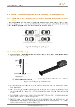
Page 15: ...n in Figure 9a a Floor standing assembly drawing b Inserting the cable into the column for installation Figure 9 Installing the pedestal for Aurora 2 Lay the column horizontally and insert the wire from the bottom hole and exit from the middle hole Figure 9b 3 After connecting the inlet line with the pile body fix the pile body on the vertical column First use two cross M6 12 Torque 1 8 2 0 N m co...

Page 16: ... in Figures 11a and Figure 11b a Fixed base b Fixed column Figure 11 Pile settings for Aurora 7 Place the rear decorative cover on the bottom plate of the column Figure 12a 8 Insert the front decorative cover into place from top to bottom and the back decorative cover and fix both sides of the front decorative cover with two M4 12 flower shaped composite screws Torque 1 4 1 6 N m with column core ...

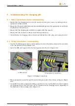
Page 17: ...d whether the cable plug and casing are intact 5 2 Wiring steps before commissioning Unscrew the M4 hexagon socket countersunk head screw at the bottom Remove the decorative cover and open the wiring window cover Insert the SIM card supported by the local operator into the slot Figure 13a a SIM card slot b Incoming wire connections Figure 13 Making Connections The incoming wire passes through the ...

Page 18: ... to connect to the backend the correct settings must be configured 5 3 2 Using third party back end If you use your own management system or the service is provided by a third party please make sure that the charging pile type is registered correctly If these settings are not properly configured in this management system the charging pile will not be connected After the correct registration of the...

Page 19: ... authorization Starting the session Ending the session 6 1 2 Swiping card to start and stop charging Starting the Charging process 1 Placing the card above the RFID reader the status light will flash blue if it has detected the card Then the EVSE will do the authentication If the authentication is successful the status light will start pulsing blue which means the charging process has begun 2 Plac...

Page 20: ...an function and scan the QR code on the front of the Aurora after successfully binded click Oneclick Charge to start charging as shown in Figure 15 Figure 15 Mobile client interface Stopping the Charging process 2 Open the StarCharge app or third party app and click the Stop button to stop charging as shown in Figure 16 If successful the status light will turn green to free mode and the charging p...

Page 21: ...sion has concluded 6 2 Indicator Description LED status indicator Meaning Constant Green Standby Constant Blue Connecting Pulsating Blue RFID card verified Breathing Blue Charging Pulsating Blue Fast flash Swiping the RFID card detected Pulsating Blue Slow flash Pause in charging requested by the EV side Constant Red Fault Wanbang Digital Energy Co Ltd 21 ...

Page 22: ...he cycle needs to be changed Please adhere to the relevant laws and regulations at the location Check Item Cycle Handling Charging connector Every month Check Leakage switch protection Every month Check Emergency stop function check Every month Test Dust inspection of control board Every month Check and Clear 7 2 Charging control logic 7 2 1 Logic of Building blocks Wanbang Digital Energy Co Ltd 2...

Page 23: ...s to 6VPWM State charging is entered 5 Relay in the charger is on Close K1 K2 Current delivery to EV has started 6 The battery is full and the vehicle asks to stop S2 off Relay is being opened no more energy is being delivered to the EV 7 Disconnect detection R2 equivalent resistance 6VPWM turns to 9VPWM Control Pilot CP voltage change to indicate charging state as been left 8 Stop sending PWM wav...

Page 24: ...ther the air switch in the distribution box trips and use the same method to recover 3 After eliminating the factors that would cause fault measure the input and output voltage of the air switch using a multimeter or a test pencil If the input voltage is about 400V when the air switch is on there is no output voltage or abnormal output voltage the air switch is broken and replace it 4 If the input...

Page 25: ...icle so Va changes from 12V to 9V At this time the charger confirms the connection and the indicator light turns green Troubleshooting tips 1 Check whether dust has accumulated in the charging connector or charging socket If so clean it 2 Check whether there is an issue with the charging connector The resistance of PP to PE is 680 Ohm when the charging connector is not inserted 3 If the above test...

Page 26: ...mines whether it is grounded by detecting whether there is a negative pulse Troubleshooting tips 1 Check whether the charger has an independent grounding system If it is not grounded sepa rately please make rectification on site and add a separate ground 2 Check whether the grounding stud is tight and whether there is corrosion If the stud is loose and the ground terminal grounding area is corrode...

Page 27: ...of Monitoring Point 1 changes from 9V to 6V At this time the power supply control device closes the contactors K1 and K2 to make the AC power supply circuit conductive Troubleshooting tips 1 It is recommended that the customer recharge and check whether it is an accidental fault 2 If the fault still exists it is recommended to drive the vehicle to an external charger or a Auto mobile Sales Service...

Page 28: ...Technical Primer Aurora For the newest version of the document please feel free to check www starcharge com Many thanks for your attention Wanbang Digital Energy Co Ltd 28 ...

Page 29: ...30 Wanbang Digital Energy Co Ltd Installation Manual ...

Page 30: ...ny Website http www starcharge com Company E mail starcharge wanbangauto com Customer service 86 400 828 0768 Customer service Preparation If you have any questions or problems please contact the company responsible for performing the electrical installation Before contacting Customer Service Check the troubleshooting measures in the Troubleshooting section of this manual ...

Reviews: