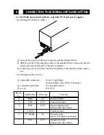
-6-
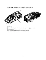
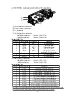
4-2. MCM300, mechanism unit (without IC controller)
1
Serial interface connector
2
Power supply connector
3
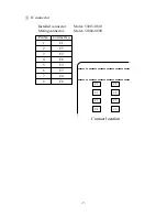
IC connector
1
Serial interface connector
Installed connector:
Molex 53015-0710
Mating connector:
Molex 51004-0700
2
Power Supply connector
Installed connector:
Molex 53015-1010
Mating connector:
Molex 51004-1000
In order to avoid malfunction, GND and P-GND are not connected internally.
Common ground connection must be made at the power supply.
Main PCB CN1
Pin No.
Signal name
Function
1
VCC
+5V Power supply for logic
2
VCC
+5V Power supply for logic
3
GND
Power supply Ground for VCC
4
GND
Power supply Ground for VCC
5
VPP 1
+5V Power supply for mechanism
6
VPP 1
+5V Power supply for mechanism
7
VPP 2
+24V Power supply for mechanism
8
VPP 2
+24V Power supply for mechanism
9
P-GND
Power supply Ground for VPP1/VPP2
10
P-GND
Power supply Ground for VPP1/VPP2
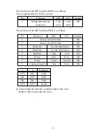
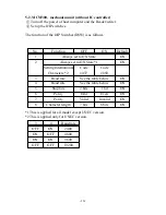
Pin No.
Signal name
Direction
Function
1
VCC
OUT
Not connected
2
GND
-
Signal ground
3
TXD
OUT
Transmitted data
4
RXD
IN
Received data
5
RTS
OUT
Request-to-send
(always ON after reset)
6
-
-
Not connected
7
RESET
IN
Not connected
Main PCB CN2
1
2
3
Summary of Contents for MCM300 SERIES
Page 1: ...VISUAL CARD READER WRITER MCP300 SERIES MCM300 SERIES PROGRAMMER S MANUAL...
Page 6: ......
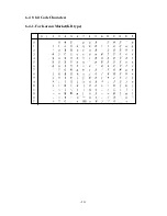
Page 18: ...12 6 4 8 bit Code Characters 6 4 1 For Korean Market KR type...
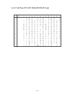
Page 19: ...13 6 4 2 Code Page 437 for EU Market US UK EC type...
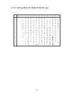
Page 20: ...14 6 4 3 Code Page 850 for EU Market US UK EC type...
Page 35: ......


