background image

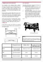
Flue Liner

Sleeve

Flue Pipe

Possible
Positions 
for access

Flue

Soot Door

Appliance Flue
Outlet

Appliance 

Debris Collection
space

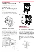
TOP FLUE EXIT

For top outlet configuration remove the hob from the
top of the stove, turn the hob upside down and place
it on the floor, taking care not to damage it.  Remove
the hob blanking plate by unscrewing the two
screws from underneath the hob.

Next remove the flue blanking plate from the top of
the stove by unscrewing the two screws, connect
this blanking plate to the rear flue outlet at the back
of the stove.  Replace the hob in the correct position.

Connect the connector pipe (not supplied) into the
top flue outlet socket at the top of the stove and
cement into place using approved fire cement ensur-
ing that no cement blocks the flue passageway. (See
Fig. 4)

Fig.3

9

Fig 4

REAR FLUE EXIT

For rear flue outlet configuration push in flue con-
nector pipe (not supplied) into flue outlet socket at
the rear of the stove and cement into place using
approved fire cement ensuring that no cement
blocks the flue passageway. (See Fig. 5)

Fig. 5

DOWN DRAUGHTS

However well designed constructed and positioned,
the satisfactory performance of the flue can be
adversely affected by down draught caused by near-
by hills, adjacent tall buildings or trees.  These can
deflect wind to blow directly down the flue  or create
a zone of low pressure over the terminal.

A suitable terminal or cowl will usually effectively
combat direct down blow but no cowl is likely to pre-
vent down draught due to a low pressure zone.
(See Fig.6)

Summary of Contents for Tara

Page 1: ...rm persons should be supervised at all times and should not be allowed to touch the hot working surfaces while in use or until the appliance has thoroughly cooled When using the boiler stove in situations where children aged and or infirm persons are present a fire guard must be used to prevent accidental contact with the stove The fireguard should be manufactured in accordance with BS 8423 2010 P...

Page 2: ...11 14 Heat Recovery Ventilation HRV 11 15 Location 12 16 Clearance to Combustibles 12 17 Floor Protection 12 18 Water Pipe Location 12 19 Plumbing Boiler Model 13 20 Pipe Thermostat 13 21 Regulations 13 22 Gravity Circuit 13 23 Injector Tee 14 24 Water Circuit Temperature 14 25 Plumbing DHW Model 15 26 Direct Domestic Cylinder 15 27 Indirect Domestic Cylinder 15 28 Stove Dimensions 16 29 Commissio...

Page 3: ... Catch 20 44 Chimney Cleaning 21 45 Glass Cleaning 21 46 Vitreous Enamel Cleaning 21 47 Cleaning a Matt Black Senotherm Stove 21 48 Frozen System 21 49 Prolonged Periods of Non Use 21 50 Fire Safety 22 51 Glass Replacement 22 52 CO Alarm 22 53 Exploded View HPB Stove 23 54 Exploded View NB Stove 24 55 Exploded View DHW Stove 25 56 Trouble Shooting 26 3 ...

Page 4: ...er the requirements of the manual Failure to comply with the Installation Requirements or Building Regulation requirements will void your warranty Waterford Stanley reserve the right to replace any part due to manufacturing defect that fails within the warranty period under the terms of the war ranty The unit must be used for normal domestic purposes only and in accordance with manufacturer s oper...

Page 5: ...uilding Regulations to have a carbon monoxide alarm fitted to any room with a solid fuel appliance Location 10 Clearance to combustible materials must be adhered to as described in the Clearance to Combustible section 11 The stove must be installed on a floor protector that covers the area under the stove and extends 18 to the front 5 to back and 5 to the sides 12 Clearance must be maintained to a...

Page 6: ...er and cleaner burning See Re Fuelling section 6 Never allow a build up of ashes in the ash pan as this will cause the grate to burn out prematurely Empty the ashpan when refuelling 7 Avoid slow burning of damp or unseasoned fuel as this will result in tarring flue ways and chim ney i e peat or timber 8 Allow adequate air ventilation to ensure plenty of air for combustion 9 Do not burn rubbish hou...

Page 7: ...ervicing this stove care should be taken to avoid the possibility of personal injury IMPORTANT WARNING This stove must not be installed into a chimney that serves any other heating appliance 7 The complete installation must be done in accor dance with current Standards and Local Codes It should be noted that the requirements and these publications may be superseded during the life of this manual P...

Page 8: ...ons will result in poor performance All register plates restricter plates damper etc which could obstruct the flue at a future date should be removed before connecting this appliance If connecting to an existing chimney with a flue diameter of more that 8 it is recommend to line the flue using a suitable stainless steel flue liner Where a masonry chimney is not available a propri etary type of 6 1...

Page 9: ...op of the stove and cement into place using approved fire cement ensur ing that no cement blocks the flue passageway See Fig 4 Fig 3 9 Fig 4 REAR FLUE EXIT For rear flue outlet configuration push in flue con nector pipe not supplied into flue outlet socket at the rear of the stove and cement into place using approved fire cement ensuring that no cement blocks the flue passageway See Fig 5 Fig 5 DO...

Page 10: ...utside the building should not be locat ed less than the dimensions specified within the Building Regulations and B S 8303 Part 1 from any part of any flue terminal These air vents must also be satisfactorily fire proofed as per Building Regulations and B S 8303 Part 1 Air vents in internal walls should not communicate with bedrooms bedsits toilets bathrooms or rooms containing a shower Air vents ...

Page 11: ... not fall within the remit for HETAS product approval Responsibility for the specification of this and for appropriate manufacturer s instruc tions is carried by the appliance manufacturer as allowed for under the Building Regulations HEAT RECOVERY VENTILATION Where a stove is to be installed in a dwelling with Heat Recovery Ventilation HRV a number of precautionary measures must be undertaken Sho...

Page 12: ... will allow air circulation and will not impede the performance of the stove LOCATION There are several conditions to be considered in selecting a location for your Stanley Tara Stove a Position in the area to be heated central locations are usually best b Allowances for proper clearances to combustibles c Allowances for proper clearances for mainte nance work FLOOR PROTECTION When installing this...

Page 13: ...nded for hot water storage and it should be connected to the boiler by 28mm diame ter flow and return piping The pipes should not exceed 7 8 meters 25ft in length and cylinder and pipework should be fully lagged The shorter the run of pipe work the more effective the water heating Fig 9 Fig 10 PIPE THERMOSTAT The fitting of a pipe thermostat to the flow pipe is essential in order to activate the w...

Page 14: ...d circulation of the hot water In some circumstances it may be possible to over heat the appliance and the water inside will boil This will be evident by the sound of a knocking noise coming from the appliance and pipes around the house If this occurs close off all air controls and manually start the central heating pump if fitted One radiator on the heating circuit should be uncon trolled to act ...

Page 15: ...sary to make the domestic hot water system more efficient Fig 14 DIRECT DOMESTIC CYLINDER A 227 Litre 60 Gallon direct domestic cylinder can be connected to the DHW stove using copper or stainless steel 28mm O D 1 flow return pipes We recommend that the cylinder is lagged along with the pipework We do not recommend the use of a direct cylinder in areas where there is a high concentration of lime o...

Page 16: ...DIMENSIONS Fig 15 BOILER STOVE DHW STOVE Fig 16 NON BOILER STOVE Fig 17 WARNING DO NOT OBSTRUCT PRIMARY AIR SUPPLY TO THE STOVE Note Dimensions stated are in millimetres and may be subject to a slight variation ...

Page 17: ...s are operating correctly and ensure that all flue connections are thoroughly sealed Fig 18 Fig 19 AIR CONTROLS The HPB model has two independent controls and the NB DHW has three controls 1 The spin valve located at the bottom end of the door controls the primary air see Fig 18 Rotate anti clockwise to open and clockwise to close 2 The window wash is located above the door see Fig 19 Push left to...

Page 18: ...s appliance has been tested using seasoned wood logs and manufactured briquetted smokeless fuel Ancit for closed appliances sized between 20g and 140g Other fuels are commercially available and may give sim ilar results Wood logs up to 380mm long are suitable All fuels should be stored under cover and kept as dry as possible prior to use Do not use fuels with a Petro coke ingredient as this may ca...

Page 19: ...tal or other non combustible container with a tight fitting lid The closed container of ashes should be placed on a non combustible material pending final disposal If ashes are buried in soil or otherwise dumped they should be retained in the closed container until they are thoroughly cooled See Fig 22 Fig 22 LIGHTING THE STOVE 1 Before lighting the stove ensure that any build up in the firebox ha...

Page 20: ...d pulling it outwards and insert cleaning brush Replace baffle before lighting fire When fitted correctly the baffle should fall forward to close onto the bottom of the boiler The appliance will not function correctly with this baffle misaligned or missing ADJUSTING THE DOOR CATCH Over time the fire door latch can loosen due to the continual compression and hardening of the rope seal between the d...

Page 21: ...should be cleaned in accordance with manufacturer s instructions Always use a brush with plastic bristles that is the correct size to reach all areas of the flue VITREOUS ENAMEL CLEANING General cleaning must be carried out when the stove is cool If this stove is finished in a high gloss vitreous enamel to keep the enamel in the best condition observe the following tips 1 Wipe over daily with a so...

Page 22: ...orner screws and clips and carefully remove the broken glass c Clean the glass recess in the door d Attach adhesive thermal tape to the perimeter of the replacement glass e Place the thermal tape side of the glass into the door recess and replace the four corner clips f Tighten screws g Replace glass only with ceramic glass 5mm thick See Fig 28 Fig 28 FIRE SAFETY To provide reasonable fire safety ...

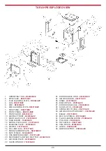
Page 23: ... F01077AXX 17 SERIAL NUMBER PLATE N00234BXX 18 DATA PLAQUE N00443AXX 19 OSA DAMPER GASKET P00101AXX 20 SECONDARY AIR WASH SHUTTER Q00247AXX 21 AIR WASH PLATE Q00564AXX 22 GLASS WINDOW T00009AXX 23 DOOR HANDLE LONG U00009AXX 24 AIR WASH KNOB U00077AXX 25 HINGE U00153AXX 26 BOILER PLUG V00016AXX 27 DOOR HANDLE AXLE V00022BXX 28 DOOR LATCH V00023AXX 29 SPRING RS 751 584 V00151AXX 30 AIR WASH SHUTTER ...

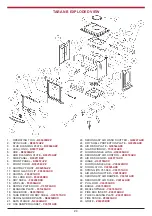
Page 24: ...H00197AXX 20 SERIAL NUMBER PLATE N00234BXX 21 DATA PLAQUE N00442AXX 22 OSA DAMPER GASKET P00101AXX 23 SECONDARY AIR WASH SHUTTER Q00247AXX 24 DRY SHELL PROTECTION PLATE Q00250AXX 25 AIR WASH PLATE Q00564AXX 26 GLASS WINDOW T00009AXX 27 DOOR HANDLE LONG U00009AXX 28 SECONDARY AIR CONTROL U00018AXX 29 AIR WASH KNOB U00077AXX 30 HINGE U00153AXX 31 DOOR HANDLE AXLE V00022BXX 32 DOOR LATCH V00023AXX 33...

Page 25: ...HELL H00197AXX 20 SERIAL NUMBER PLATE N00234BXX 21 DATA PLAQUE N00566AXX 22 OSA DAMPER GASKET P00101AXX 23 SECONDARY AIR WASH SHUTTER Q00247AXX 24 DRY SHELL PROT PLATE Q00250AXX 25 AIR WASH PLATE Q00564AXX 26 GLASS WINDOW T00009AXX 27 DOOR HANDLE Long U00009AXX 28 SECONDARY AIR CONTROL U00018AXX 29 AIR WASH KNOB U00077AXX 30 HINGE U00153AXX 31 DOOR HANDLE AXLE V00022BXX 32 DOOR LATCH V00023AXX 33 ...

Page 26: ... carpentry off cuts plywood pallets etc Smokes When Lighting Up Flue duct is cold Burn paper and kindling to increase heat Smokes While Burning Draught is insufficient Down Draught Room is in decompression Consult a chimney specialist Check that the flue is not obstruct ed sweep if necessary Install an anti down draught cowl Consult your dealer In houses equipped with Mechanical Ventilation an out...

Page 27: ...27 NOTES ...

Page 28: ...28 Manufactured by Waterford Stanley Ltd Unit 401 403 IDA Industrial Estate Cork Road Waterford Ireland Tel 051 302300 Fax 051 302315 Rev 005 YS270717 Item No N00154AXX ...

Reviews: