background image

ENGLISH (

Original Instructions)

16

PACKAGE CONTENTS

The package contains:

1 Chipping hammer

1 Kitbox

1 Grease tube

1 Spanner

1 Instruction manual


♦ Check for damage to the tool, parts or accessories 

which may have occurred during transport.


♦ Take the time to thoroughly read and understand this 

manual prior to operation.

ELECTRICAL SAFETY 

Your tool is double insulated; therefore no earth wire 

is required. Always check that the main voltage 

corresponds to the voltage on the rating plate.


Warning!

 If the power cord is damaged, it must be 

replaced by the manufacturer, authorized Stanley 

Service Center or an equally qualified person in 

order to avoid damage or injury. If the power cord is replaced 

by an equally qualified person, but not authorized by 

Stanley the warranty will not be valid.  

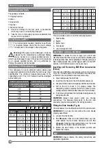
USING AN EXTENSION CABLE 

If it is necessary to use an extension cable, please used 

an approved extension cable that fits the tool’s power input 

specifications. The minimum cross-sectional area of the 

conducting wire is 1.5 sq. mm. Cables should be untangled 

before reeling up.

Cable cross-sectional 

area (mm2) Cable rated 

current (Ampere) 

Cable cross-sectional 

area (mm2) Cable rated 

current (Ampere) 

0.75

6

1.00

10

1.50

15

2.50

20

4.00

25

                                             Cable length (m)

7.5 15

25

30

45

60

Voltage

Amperes Cable rated current (Ampere)

110-127

0 - 2.0

6

6

6

6

6

10

2.1 - 3.4

6

6

6

6

15 15

3.5 - 5.0

6

6

10 15 20 20

5.1 - 7.0

10 10 15 20 20 25

7.1 - 12.0 15 15 20 25 25

-

12.1 - 

20.0

20 20 25

-

-

-

220-240

0 - 2.0

6

6

6

6

6

6

2.1 - 3.4

6

6

6

6

6

6

3.5 - 5.0

6

6

6

6

10 15

5.1 - 7.0

10 10 10 10 15 15

7.1 - 12.0 15 15 15 15 20 20

12.1 - 20.0 20 20 20 20 25
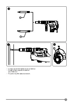
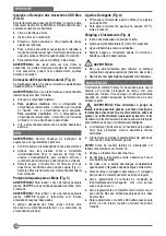
-

FEATURES (FIG. A) 

This tool includes some or all of the following features. 

1.  Side handle

2.  Switch

3.  Barrel cover

4.  Tool sleeve

5.  Lube oil-injection inlet

ASSEMBLY AND ADJUSTMENT

WARNING!

 To reduce the risk of injury, turn unit off and 

disconnect machine from power source before installing and 

removing accessories, before adjusting or changing set-ups or 

when making repairs. Be sure the trigger switch is in the OFF 

position. An accidental start-up can cause injury. 

Inserting and Removing SDS Max Accessories 

(FIG. A) 

This tool uses SDS Max accessories (refer to the inset in 

Fig. A for a cross-section of an SDS Max bit shank). We 

recommend to use professional accessories only.


♦ Clean and grease the bit shank.


♦ Insert the bit shank into the bit holder/tool sleeve (4).


♦ Push the bit down and turn it slightly until it fits into the slots.


♦ Pull on the bit to check if it is properly locked. The 

hammering function requires the bit to be able to move 

axially several centimetres when locked in the tool holder.


♦ To remove a bit pull back the tool holder/locking sleeve (4) 

and pull out the bit. 

WARNING!

 Always wear gloves when you change 

accessories. The exposed metal parts on the tool and 

accessory may become extremly hot during operation. 

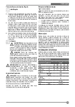
Fitting the Side Handle (Fig. A) 

The side handle (1) can be fitted to suit both RH- and LH-users.

WARNING!

 Do not use the tool without the side handle 

properly assembled. 


♦ Loosen the side handle.


For RH-users:

 Slide the side handle clamp over the 

collar behind the tool holder, handle at the left. 

For 

LH-users:

 Slide the side handle clamp over the collar 

behind the tool holder, handle at the right. 


♦ Rotate the side handle to the desired position and 

tighten the handle.

USE  

WARNING!

 Always observe the safety instructions and 

applicable regulations.

Summary of Contents for SHM5

Page 1: ...Page 14 SHM5 MANUAL DE INSTRUCCIONES MANUAL DE INSTRU ES INSTRUCTIONS MANUAL ADVERTENCIA LEASE ESTE INSTRUCTIVO ANTES DE USAR EL PRODUCTO ADVERT NCIA LEIA ESTAS INSTRU ES ANTES DE USAR O PRODUTO WARNI...

Page 2: ...2 A 1 4 2 3 5 A B 1 2 4 4 6 La imagen puede diferir ligeramente de la unidad real A imagem pode ser ligeiramente diferente para unidade real The picture may differ slightly to actual unit...

Page 3: ...3 B D 6 7 C 8 La imagen puede diferir ligeramente de la unidad real A imagem pode ser ligeiramente diferente para unidade real The picture may differ slightly to actual unit...

Page 4: ...eriores La utilizaci n de un cable alargador adecuado para su uso en exteriores reduce el riesgo de una descarga el ctrica f Si fuera inevitable la utilizaci n de una herramienta el ctrica en un lugar...

Page 5: ...momento No intente operar la herramienta a menos que la est sosteniendo con ambas manos La operaci n de esta herramienta con una mano puede causar p rdida de control Topar con materiales como varillas...

Page 6: ...r lo tanto no requiere una toma a tierra Compruebe siempre que la tensi n de la red corresponda al valor indicado en la placa de caracter sticas Advertencia Si el cable de alimentaci n esta da ado lo...

Page 7: ...reducir el riesgo de lesiones personales graves use SIEMPRE la posici n adecuada de las manos como se indica ADVERTENCIA Para reducir el riesgo de lesiones personales graves sostenga SIEMPRE la herram...

Page 8: ...ta herramienta accesorios que no sean Stanley el uso de dichos accesorios puede ser peligroso Para reducir el riesgo de lesiones use s lo los accesorios Stanley recomendados con este producto Hay vari...

Page 9: ...a el trica num local mido utilize um Dispositivo de Corrente Residual RCD A utiliza o de um RCD reduz o risco de choque el trico Nota O termo Dispositivo de Corrente Residual RCD pode ser substitu do...

Page 10: ...igoso Segure com firmeza a empunhadura antes de usar a ferramenta Verifique que o cinzel esteja bem firme antes de usar a ferramenta Em climas frios ou quando a ferramenta n o foi usada por um per odo...

Page 11: ...arado ou substitu do por uma pessoa qualificada mas n o autorizada pela Stanley a garantia ser perdida USO DO CABO DE EXTENS O Caso seja necess rio usar um cabo de extens o use um aprovado e conforme...

Page 12: ...menta com firmeza antecipando rea es inesperadas A posi o adequada das m os requer colocar uma m o sobre a empunhadura lateral 1 e a outra m o na empunhadura principal Ligado e Desligado Fig A TPara u...

Page 13: ...e n o sejam aqueles oferecidos pela Stanley n o foram testados com este produto o uso dos mesmos pode ser perigoso Para reduzir o risco de les es use apenas os acess rios Stanley recomendados com este...

Page 14: ...under the influence of drugs alcohol or medication A moment of inattention while operating power tools may result in serious personal injury b Use personal protective equipment Always wear eye protec...

Page 15: ...ra cushion and limit exposure by taking frequent rest periods Note Mains voltage When connecting to the mains it is imperative to verify if the voltage of the mains matches that of the power tool If t...

Page 16: ...20 20 20 25 FEATURES FIG A This tool includes some or all of the following features 1 Side handle 2 Switch 3 Barrel cover 4 Tool sleeve 5 Lube oil injection inlet ASSEMBLY AND ADJUSTMENT WARNING To re...

Page 17: ...it is integral and then switch off Unplug the charger before cleaning it Your charger does not require any maintenance apart from regular cleaning Regularly clean the ventilation slots in your applia...

Page 18: ...duct recycling services Notes Stanley s policy is one of continuous improvement to our products and as such we reserve the right to change product specifications without prior notice Standard equipmen...

Page 19: ...ker de Colombia S A Carrera 85D 51 65 Bodega 23 Complejo Log stico San Cayetano Bogot Colombia Tel 744 7100 Solamente para prop sito de Chile Importado por Black Decker de Chile S A Av Pdte Eduardo Fr...

Reviews: