9
INJECTOR TEE
Where the gravity and central heating circuits join
together to return to the Cooker we recommend the
use of an injector tee connection, situated as close
to the unit as possible. This type of tee encourages
a stable flow of hot water through both circuits and
helps to prevent priority being given to the stronger
flow, which is most commonly the pumped central
heating circuit. (See fig. 6).
WATER CIRCUIT TEMPERATURE
The return water temperature should be maintained
at not less than 40
o
C so as to avoid condensation on
the boiler and return piping. Fitting a pipe thermostat
to the return from the gravity circuit and wiring it into
the pump control will ensure that no cold water will
be returned from the central heating circuit before
the water from the gravity circuit has warmed up to
the common return pipe and boiler. If this is not
sufficient to keep the boiler temperatures above the
required minimum, a three-way mixing valve may be
fitted to the flow pipe to divert some hot water
straight back into the return. Such a valve can be
operated either manually or electrically in
conjunction with a return pipe thermostat.
PIPE THERMOSTAT
Another advantage of fitting a pipe thermostat on the
gravity return is that priority will always be given to
the domestic hot water supply.
FUELS
The Cooker output levels are assessed on standard
House Coal of good quality. Reduced outputs will
result when fuels of lower calorific values are used.
Wood logs up to 38cm (15”) long are suitable.
All fuels should be stored under cover and kept as
dry as possible prior to use.
SECONDARY AIR PIPE
The Secondary Air Pipe is for use with House Coal,
Timber and Peat Fires only. It must be removed
when burning Anthracite or other smokeless fuels.
CIRCULATING PUMP
It is recommended that the selected pump be of a
proprietary type and manufacture, and be adequate
to give the required temperature differential between
the flow and return. The pump should be able to
meet the requirements of the system design and be
fitted in a readily accessible position. It may be
positioned either on the boiler section flow or the
return, depending on the system design.
Isolating valves (preferably of the keyless type) must
be fitted to the inlet and outlet of the circulating
pump to facilitate service and replacement of pump
without draining the system.
Pipework not forming part of the useful heating
surface should be insulated to help prevent heat
loss and possible freezing, particularly where pipes
are run through roof spaces and ventilated
underfloor spaces. Cisterns situated in areas which
may be exposed to freezing conditions should also
be insulated.
Draining taps must be located in accessible
positions which permit the draining of the whole
system, including the appliance and hot water
storage vessel. Draining taps should be at least
1
/
2
in. (12.5mm) BSP nominal size and be in
accordance with BS 2879.
The appliance boiler section should be connected to
a cistern water supply, subject to a maximum head
of 18.25m (60ft).
The heating system must be designed (and adjusted
if necessary) to give a temperature differential
across the boiler at full output of 10
o
- 14
o
C (18
o
-
35
o
F). The use of horizontal pipe runs should be
avoided wherever possible in order to prevent the
collection of air in the system. If horizontal runs are
unavoidable the pipes should rise upwards in the
direction away from the appliance.
FUEL CALORIFIC VALUE
Anthracite 25 - 50mm
Calorific Value 8.2 kW/KG = 14,000 BTUS/LB
House Coal 25 - 75mm
Calorific Value 7.2 kW/KG = 12,300 BTUS/LB
Timber - Firebox Size
Calorific Value 5.0 kW/KG = 8,600 BTUS/LB
Peat Briquettes -
Calorific Value 4.8 kW/KG = 8,300 BTUS/LB
Bog Peat -
Calorific Value 3.4 kW/KG = 6,000 BTUS/LB
Fig. 6
INHIBITORS
We strongly recommend the use of corrosion
inhibitors and anti-freeze solution in the system.
Use only quantities specified by the inhibitor
manufacturer. Add inhibitor only after flushing
when finally re-filling the system. Refer to BS 7953.
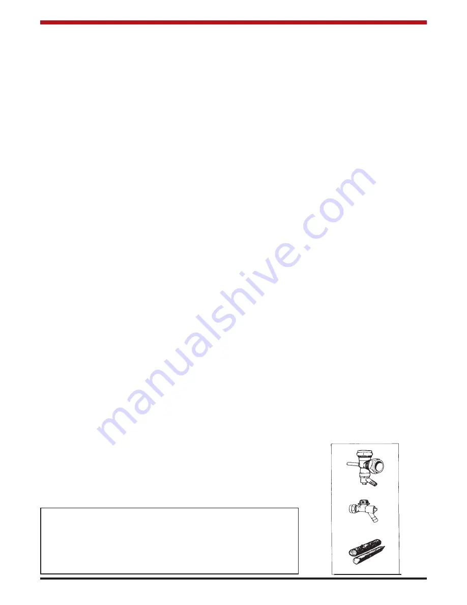
Injector Tee Samples
Typical Logs


