background image

Phone: (408)744-9040

www.thinkSRS.com

PS300 Series High Voltage Power Supplies

Analog Monitor and Control

2 – 5

The current monitor output BNC provides a 0 to +10 volt output for 
0 to full-scale output, regardless of the output polarity. 

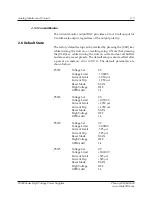
The factory default setup can be recalled by pressing the [CLR] key 
while turning the unit on, or recalling setup 0. Note that pressing 
the [CLR] key while turning the unit on will also clear all bu

 ers 

and erase any saved presets. The default setup is also recalled a  er 
a power on memory error (

ERR 1

). The default parameters are 

shown below.

PS355    

Voltage Set  


0 V

  Voltage 

Limit 


10,000 V

  Current 

Limit 


1,050 

µ

A

  Current 

Trip 


1,050 

µ

A

  Reset 

Mode 


 MAN

  High 

Voltage 


 OFF

  GPIB 

Addr 


 14

PS365    

Voltage Set  


0 V

  Voltage 

Limit 


 +10,000 

V

  Current 

Limit 


 +1,050 

µ

A

  Current 

Trip 


 +1,050 

µ

A

  Reset 

Mode 


 MAN

  High 

Voltage 


 OFF

  GPIB 

Addr 


 14

PS370    

Voltage Set  


0 V

  Voltage 

Limit 


20,000 V

  Current 

Limit 


525 

µ

A

  Current 

Trip 


525 

µ

A

  Reset 

Mode 


 MAN

  High 

Voltage 


 OFF

  GPIB 

Addr 


 14

PS375    

Voltage Set  


0 V

  Voltage 

Limit 


 +20,000 

V

  Current 

Limit 


 +525 

µ

A

  Current 

Trip 


 +525 

µ

A

  Reset 

Mode 


 MAN

  High 

Voltage 


 OFF

  GPIB 

Addr 


 14


2.5.3  Current Monitor

2.6  Default State

Summary of Contents for PS355

Page 1: ...Operation and Service Manual High Voltage Power Supplies PS355 PS365 PS370 PS375 Stanford Research Systems Revision 1 0 December 2008 ...

Page 2: ...ty service or repair this product must be returned to a Stanford Research Systems authorized service facility Contact Stanford Research Systems or an authorized representative before returning this product for repair Contact Information Stanford Research Systems Inc 1290 D Reamwood Avenue Sunnyvale CA 94089 USA Phone 408 744 9040 Fax 408 744 9049 www thinkSRS com info thinkSRS com Information in t...

Page 3: ...meters 2 2 2 2 Reset 2 3 2 3 Store and Recall 2 3 2 4 Error Messages 2 4 2 5 Analog Monitor and Control 2 4 2 6 Default State 2 5 3 Remote Operation 3 1 3 1 Index of Common Commands 3 2 3 2 Alphabetic List of Commands 3 3 3 3 Introduction 3 4 3 4 Commands 3 4 3 5 Status Model 3 12 3 6 Status Reporting 3 13 4 Troubleshooting 4 1 4 1 Troubleshooting the PS300 4 2 Contents ...

Page 4: ...Stanford Research Systems PS300 Series High Voltage Power Supplies Contents ii ...

Page 5: ...to a protective ground ThePS300usesadetachable three wirepowercordforconnectionto the power source The exposed metal parts of the box are connected to the power ground to protect against electrical shock Always use an outlet which has a properly connected protective ground The rear panel high voltage connector and the BNC shields are also connected to chassis ground The PS300 series supplies CANNO...

Page 6: ...ower Supplies Contents iv Symbol Description Alternating current Caution risk of electric shock Frame or chassis terminal Caution refer to accompanying documents Earth ground terminal Battery Fuse On supply Off supply Symbols you may find on SRS products ...

Page 7: ...elect a digit Front panel indicators are represented as Overload The state of a switch is represented in italics as ON Remote command names are represented as IDN Literal text other than command names is represented as OFF Remote command examples will all be set in monospaced font In these examples data sent by the host computer is set as straight teletype font while responses received by the host...

Page 8: ...scale voltage Output ripple rms 0 01 of full scale max Current limit range 0 to 105 of full scale Current trip range 0 to 105 of full scale Trip response time 10ms Current set accuracy 1µA Current resolution 1µA Current display accuracy 1µA typ 2µA max Stability 0 01 per hr 0 03 per 8 hrs Temperature dri 50ppm C 0 to 50 C typ Protection Arc and short circuit protected programmable voltage limit cu...

Page 9: ...dance 1MΩ Accuracy 0 2 of full scale Update rate 87 5Hz Mechanical HV connector Kings type 1064 1 PS355 and PS365 Kings type 1764 1 PS370 and PS375 Mating connector Kings type 1065 1 PS355 and PS365 Kings type 1765 1 PS370 and PS375 Dimensions 8 1 3 5 16 WHD Weight 8lbs Power 50W 90 to 264VAC 47 to 63Hz Warranty One year parts and labor on defects in materials or workmanship All performance specif...

Page 10: ...Phone 408 744 9040 www thinkSRS com PS300 Series HighVoltage Power Supplies General Information viii ...

Page 11: ... 1 2 1 1 1 Power Bu on 1 2 1 1 2 High Voltage Enable Switch 1 2 1 1 3 Numeric Displays 1 3 1 1 4 Select Enter Clear 1 3 1 1 5 Numeric and Cursor Keys 1 3 1 1 6 Instrument Status 1 3 1 1 7 Other Keys 1 3 1 1 8 Store and Recall 1 4 1 2 Rear Panel 1 4 1 2 1 Power Entry Module 1 4 1 2 2 High Voltage Connector 1 4 1 2 3 Analog I O 1 5 1 2 4 IEEE 488 Port 1 5 1 2 5 RS 232 Port 1 5 ...

Page 12: ...nfiguration and any saved presets are lost and the default se ings are used If the default se ings are desired hold down the clear key CLR while turning on the power Note that this will clear out all buffers and erase any saved presets The High Voltage enable switch has three positions that perform several functions In the down position the high voltage is OFF and all trips are cleared In this posi...

Page 13: ...start over When the desired value is displayed ENTER updates the unit s actual se ing and stops the LED from flashing All parameters may be adjusted using the cursor or numeric keys When using the cursor the digit being adjusted in the center display will flash The and keys increment and decrement the digit The and keys select the flashing digit When using direct numerical entry simply press the n...

Page 14: ...ING This unit contains hazardous voltages Please make certain that the high voltage is completely discharged before removing or connecting the high voltage cable High voltage cables can store charge If they are disconnected from the supply while high voltage is present electric shock can occur which may cause injury or damage the unit The high voltage output connector is a Kings type 1064 1 PS355 ...

Page 15: ...arity To select the rear SET analog high voltage control press SELECT on the front panel until REAR is selected and then use the and keys to choose between Front and Rear Press ENTER to confirm the selection The 24 pin IEEE 488 GPIB connector allows computer control of PS300 series supplies The address is set from the front panel using the GPIB key The 9 pin female D sub connector allows computer ...

Page 16: ...Stanford Research Systems PS300 Series High Voltage Power Supplies Instrument Overview 1 6 ...

Page 17: ...meters 2 2 2 1 1 Se ing the Output Voltage 2 2 2 1 2 Se ing the Voltage Limit 2 2 2 1 3 Se ing the Current Limit 2 3 2 1 4 Se ing the Current Trip 2 3 2 2 Reset 2 3 2 3 Store and Recall 2 3 2 4 Error Messages 2 4 2 5 Analog Monitor Control 2 4 2 5 1 Voltage Set 2 4 2 5 2 Voltage Monitor 2 4 2 5 3 Current Monitor 2 4 2 6 Default State 2 5 ...

Page 18: ... any error message If the REAR status LED is lit the high voltage is programmed from the analog set input on the rear panel In this mode if the center display is showing voltage SET the displayed value is the present value of the high voltage programmed by the 0 to 10 V input and cannot be adjusted from the front panel The voltage limit is a protection feature to prevent the output voltage from be...

Page 19: ...urrent trips are cleared just like voltage trips The reset mode determines how the unit responds a er a voltage or current trip In MAN manual mode the high voltage remains OFF a er a trip and requires that the operator turn it back ON In AUTO automatic mode the unit waits until the later of the time for the output voltage to fall to 0 5 of full scale or two seconds and then turns the high voltage ...

Page 20: ...are watchdog When configured for rear control see 1 2 3 the rear panel SET voltage will set the output voltage When enabled the REAR rear panel status LED is lit and the output voltage being set by the rear panel is displayed in the middle display when it is showing voltage SET The voltage limit is still active and does not allow the rear panel voltage to set the output above the voltage limit If ...

Page 21: ... setup is also recalled a er a power on memory error ERR 1 The default parameters are shown below PS355 Voltage Set 0 V Voltage Limit 10 000 V Current Limit 1 050 µA Current Trip 1 050 µA Reset Mode MAN High Voltage OFF GPIB Addr 14 PS365 Voltage Set 0 V Voltage Limit 10 000 V Current Limit 1 050 µA Current Trip 1 050 µA Reset Mode MAN High Voltage OFF GPIB Addr 14 PS370 Voltage Set 0 V Voltage Li...

Page 22: ...Stanford Research Systems PS300 Series High Voltage Power Supplies Guide to Operation 2 6 ...

Page 23: ... 3 3 1 Power On Configuration 3 4 3 3 2 Buffers 3 4 3 4 Commands 3 4 3 4 1 Command Syntax 3 4 3 4 2 Notation 3 5 3 4 3 Examples 3 5 3 4 4 Output Control Commands 3 6 3 4 5 Se ing Control Commands 3 6 3 4 6 Interface Control Commands 3 8 3 4 7 Status Reporting Commands 3 10 3 5 Status Model 3 12 3 6 Status Reporting 3 13 3 6 1 Serial Poll Status Byte 3 13 3 6 2 Standard Event Status Byte 3 14 3 6 3 ...

Page 24: ...Output Current VOUT 3 6 Output Voltage Setting Control Commands RCL i 3 6 Recall SAV i 3 7 Save ILIM x 3 7 Current Limit ITRP x 3 7 Current Trip SMOD i 3 7 V Set Mode TCLR 3 7 Trip Clear TMOD i 3 8 Trip Mode VLIM x 3 8 Voltage Limit VSET x 3 8 Voltage Set Interface Control Commands RST 3 8 Reset IDN 3 9 Identify OPC 3 9 Operation Complete LERR 3 9 Last Error Status Reporting Commands CLS 3 10 Clea...

Page 25: ... Power On Status Clear RCL i 3 6 Recall RST 3 8 Reset SAV i 3 7 Save SRE i 3 11 Service Request Enable STB i 3 11 Status Byte H HVOF 3 6 High Voltage Off HVON 3 6 High Voltage On I ILIM x 3 7 Current Limit IOUT 3 6 Output Current ITRP x 3 10 Current Trip L LERR 3 9 Last Error S SMOD i 3 7 V Set Mode T TCLR 3 7 Trip Clear TMOD i 3 8 Trip Mode V VLIM x 3 8 Voltage Limit VOUT 3 6 Output Voltage VSET x...

Page 26: ...g bytes in a 128 character input buffer Characters accumulate in the input buffer until a command terminator either CR or LF is received at which point the mes sage is parsed and executed Query responses are buffered in a 128 character output queue If the input buffer overflows then all data in both the input buffer and output queue are discarded and an error is reported in the Standard Event Status By...

Page 27: ...s received The following table summarizes the notation used in the command descriptions Symbol Definition i Unsigned integer x Assigned value Required for queries illegal for set commands var Parameter always required var Parameter required for set commands illegal for queries var Optional for both set and query commands Each command is provided with a simple example illustrating its usage In thes...

Page 28: ...ample HVON IOUT Output Current The IOUT query returns the actual output current in amperes This is the same value shown on the front panel meter The value is always returned as an unsigned number regardless of the polarity of the power supply Example IOUT 4 78E 4 VOUT Output Voltage The VOUT query returns the actual output voltage in volts This is the same value shown on the front panel meter The ...

Page 29: ...t The ITRP command sets queries the value of the current trip to x in amperes ITRP may be set from 0 to 105 of full scale Example ITRP 5 25E 4 SMOD i Rear Programming Mode The SMOD command sets queries the VSet se ing mode SMOD 0 means that the voltage value is controlled by the front panel se ing while SMOD 1 indicates that the output is controlled by the rear panel VSET voltage control input Not...

Page 30: ...Set The VSET command sets queries the value of the voltage se ing to x in volts If SMOD 1 rear panel control is enabled then se ing the VSET command returns an error The value x must match the polarity of the power supply When SMOD 0 front panel control the VSET query returns the set parameter not the measured output voltage see VOUT 3 4 4 When SMOD 1 rear panel control the VSET query returns the ...

Page 31: ...pause until all pending operations are complete The OPC query will return the value 1 when operations are complete while the OPC set command will set the OPC bit bit 0 in the ESR register Example OPC 1 LERR Last Error The LERR query returns the error code of the last remote interface error A list of the possible error codes are as follows Code Meaning 10 Illegal value execution 100 Lost data query...

Page 32: ...dent Example IDN LERR 113 3 4 7 Status Reporting Commands CLS Clear Status The CLS common command clears all status registers Example CLS ESE i Standard Event Enable The ESE common command sets queries the standard event status enable register to i The parameter i is the decimal value for the enable register and can range from 0 to 255 Example ESE 16 ESR i Standard Event The ESR common command que...

Page 33: ...ues at power down This allows the generation of a service request at power up for example Example PSC 1 SRE i Service Request Enable The SRE common command sets queries the value of the service request enable register to i Example SRE 6 STB i Standard Byte The STB common command query reads the value of the serial poll status byte If the optional parameter i is present the value of bit i is return...

Page 34: ...t can only be cleared by reading its value Event register names end with SR Enable Registers These read write registers define a bitwise mask for their corre sponding event register If a bit position is set in an event register while the same bit position is also set in the enable register then the corresponding summary bit message is set Enable register names end with SE At power on all status re...

Page 35: ...ip Indicates a voltage trip has occurred 2 itrip Indicates a current trip has occurred 3 ilim Indicates a current limit condition has occurred 4 MAV Indicates GPIB output queue is non empty 5 ESB Indicates an unmasked bit in the standard status byte has been set 6 RQS MSS SRQ bit 7 hvon Indicates high voltage is on The PS300 will make a service request SRQ whenever one of these bits is set and the...

Page 36: ...t in the standard status register is set and the corresponding bit in the standard status enable register is set then the ESB bit in the serial poll register is set If an error occurs due to an incomplete command the following er ror messages will appear on the middle display Err6 Syntax Error Over GPIB The command has an error in syntax or was unrecognizable This is the same error as seen in the ...

Page 37: ...Phone 408 744 9040 www thinkSRS com PS300 Series High Voltage Power Supplies Status 3 15 reading back all the bytes This is the same error seen in the Query Error bit 2 of the Standard Event Status Byte ...

Page 38: ...Stanford Research Systems PS300 Series High Voltage Power Supplies Remote Operation 3 16 ...

Page 39: ...tronics technician through troubleshooting the PS300 Series Power Supplies 4 1 Troubleshooting the PS300 4 2 4 1 1 Power On Reset 4 2 4 1 2 Stuck Keys 4 2 4 1 3 No High Voltage 4 2 4 1 4 Repeated Trips 4 2 4 1 5 Rear Panel Voltage Set 4 3 4 1 6 Front Panel Test 4 3 4 1 7 Calibration 4 3 ...

Page 40: ...ssage likeErr2 andthekeyboardisunresponsive check to see if a key is stuck down If so gently flick the stuck key back to the center of its hole Check to make sure that the HIGH VOLTAGE LED is ON If the HIGH VOLTAGE LED is OFF check the following 1 Check the voltage limit and current trip levels to see that they are not too low for your load If the HIGH VOLTAGE LED is ON but the output voltage is z...

Page 41: ... see all indicators and numeric segments except for HV ON lit By pressing the arrow key individual annunciator lamps will light one by one across the front panel except again for the HV ON indicator which is controlled directly by hardware wired to the high voltage enable circuitry Continue pressing the key to then test the individual segments of the numeric displays A er the final segment the dec...

Page 42: ...Stanford Research Systems PS300 Series High Voltage Power Supplies Troubleshooting 4 4 ...

Reviews: