


12
Standard Pump Operating Instructions and Parts Manual (OIPMS0611)
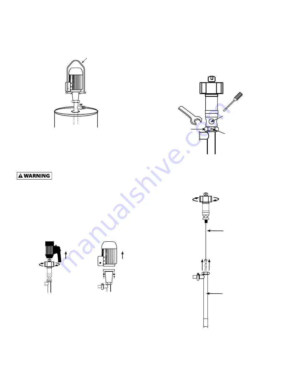
7
. Once the pump is fully assembled and all connections are
fastened, insert the pump into the drum or tank. Pump can
be suspended from hoisting system using a pump hanger
(P/N: 8430) .
8. It is recommended to attach a suitable hose or pipe to the
pump discharge.
9. If you opt to use a hose, fasten the hose to the hose
barb with a suitable hose clamp that exceeds the pump
discharge pressure.
Make sure the hose meets the pump
discharge pressure requirements (SP-800-751
or SP-800-1851=87 psi (6 bar)) / (SP-800-752=174 psi (12,1 bar)).
It is recommended to use a hose that is rated 4 x the pump
discharge pressure. Ex: 87 x 4= 348 psi (24,3 bar).
Maintenance
DISASSEMBLY / CLEANING PROCEDURES (SP-800SR &
SP-800DD)
1 . Remove motor from pump tube . For models SP-800SR:
loosen Hex Nut in clockwise rotation (see Figure 3). For
models SP-800DD: loosen (4) bolts that attach the pump to
the motor (see Figure 4).
2. Loosen set screw on side of Hex Nut (see Figure 5).
3. Place a screwdriver (or similarly shaped object) in the
mechanical seal inspection port (see Figure 5).
4. Use a large wrench to loosen the Hex Nut while
simultaneously holding the screwdriver in the seal
inspection port (see Figure 5) .
5. Once the Hex Nut is loosened, remove the outer tube from
the drive shaft assembly (see Figure 6).
Figure 5
Mechanical Seal
Inspection Port
Set Screw
Hex Nut
Outer Tube
Assembly
Drive Shaft
Assembly
Figure 6
P/N: 8430
Figure 4
NOTE:
Remove 4 bolts
from motor flange .
Figure 3
NOTE:
Remove motor
by turning hex nut
clockwise