background image

SET UP INSTRUCTIONS

11

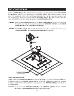
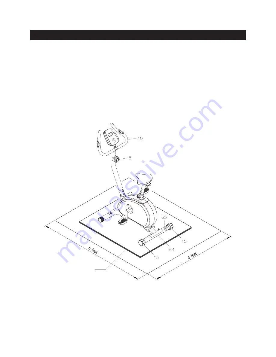
Place the 

AVARI® Upright Bike

 in the area where it will be used. It is recommended that the 

AVARI® 

Upright Bike

 be placed on an equipment mat. The 

AVARI® Upright Bike


is approximately 33 inches 

long x 20.1 inches wide x 45.7 inches tall. (These dimensions may vary up to one inch.) An area 4 feet 

wide x 5 feet long is required for safe operation of the 

AVARI® Upright Bike.

 Make sure that adequate 

space is available for access to and passage around the 

AVARI® Upright Bike.

LEVELING: 

Adjust  the 

LEVELING CAPS(15)

  on  the 

REAR STABILIZER(64)

  so  the  bike  sits  on  the 

floor  without  rocking.  Remove  and  reposition  the 

LEVELING CAPS(15)

  on  the 

REAR 

STABILIZER(64)

 to level the 

AVARI® Upright Bike.

MOVING: 

The 

AVARI® Upright Bike

 must be lifted to be moved. Two people are required to grasp 

the 

HANDLEBAR(10)

 and the 

REAR STABILIZER(64),

 lift and move.

FUNCTION INSPECTION:

Visually inspect the 

AVARI® Upright Bike

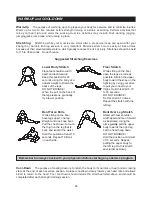
 to verify that assembly is as shown in the above illustration. 

Check  the  function  of  the 

AVARI® Upright Bike

  by  turning  the  crank  slowly  through  one  complete 

revolution to verify that the drive train functions properly. Adjust the 

TENSION KNOB(8)

 and verify that it 

functions properly.

CAUTION: 

Locate and read the 

WARNING LABEL(65)

 on the 

AVARI® Upright Bike.

 Make sure that all 

users read the 

WARNING LABEL(65)

 before using the product.

Equipment Mat

(not included)

Summary of Contents for AVARI Upright Bike

Page 1: ...tamina Products Inc 2012 08 Exercise can present a health risk Consult a physician before beginning any exercise program with this equipment If you feel faint or dizzy immediately discontinue use of t...

Page 2: ...d 12 Each user should adjust the seat per instructions on page 12 13 Do not attempt to adjust the seat while you are on the AVARI Upright Bike 14 Consult a physician prior to commencing an exercise pr...

Page 3: ...ur Customer Service Department toll free number 1 800 375 7520 Monday Thursday 7 30 A M 5 00 P M Central Time Friday 8 00 A M 3 00 P M Central Time TELEPHONE CUSTOMER SERVICE Tel 1 800 375 7520 FAX CU...

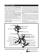
Page 4: ...ifestyle Before reading further please review the drawing below and familiarize yourself with the parts that are labeled Read this manual carefully before using the AVARI Upright Bike Although Stamina...

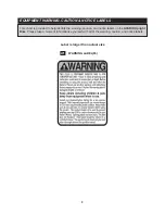
Page 5: ...s provided to help identify the warning caution and notice labels on the AVARI Upright Bike Please take a moment to familiarize yourself with all of the warning caution and notice labels EQUIPMENT WAR...

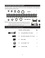
Page 6: ...the bolts and screws NOTICE The length of all bolts and screws except those with flat heads is measured from below the head to the end of the bolt or screw Flat head bolts and screws are measured fro...

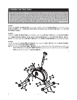
Page 7: ...3 00 P M Central Time on Friday STEP 1 Attach the FRONT STABILIZER 4 the shorter stabilizer with the ENDCAPS 13 to the front of the MAIN FRAME 1 with CARRIAGE BOLTS M8x1 25x60mm 16 WASHERS M8 27 and...

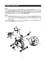
Page 8: ...he SEAT SLIDER 59 into the SEAT POST 3 Refer to detail view B Continue to slide the SEAT SLIDER 59 slowly until the Threaded Rod of the SECURING BRACKET 61 drops and goes through the hole in the SEAT...

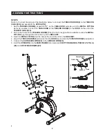
Page 9: ...SION CABLE 39 2 Pull on the Cable of the TENSION KNOB 8 firmly so that enough cable is available to allow the METAL FITTING to go through the slot in the top of the BRACKET 3 Insert the METAL FITTING...

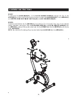
Page 10: ...8x1 25x15mm 48 and ARC WASHERS M8 49 STEP 8 Install two AA batteries into the METER 14 the batteries are not included See page 13 for detailed battery installation instructions Plug the EXTENSION WIRE...

Page 11: ...without rocking Remove and reposition the LEVELING CAPS 15 on the REAR STABILIZER 64 to level the AVARI Upright Bike MOVING The AVARI Upright Bike must be lifted to be moved Two people are required to...

Page 12: ...ts securely on the SEAT POST 3 If your leg is too straight or if your foot cannot touch the pedal when extended at the downstroke you will need to lower the seat If your leg is bent too much you will...

Page 13: ...yed If the heart symbol does not appear relax your grip or change your grip on the pulse sensors FUNCTIONS SCAN TIME SPEED DISTANCE CALORIES ODOMETER RPM PULSE Pedal movement or push the MODE button A...

Page 14: ...resistance changes 2 Use a wrench to verify that the pedals are tightened securely If tightening is required remember that the left pedal has left hand threads and is tightened by turning counterclock...

Page 15: ...of your maximum heart rate zone Start at the lower intensity and build up to higher intensity as you become more aerobically fit If you feel dizzy or lightheaded you should slow down or stop exercisin...

Page 16: ...cool down should include the stretches listed above and should be completed after each strength training session Lower Body Stretch Place feet shoulder width apart and lean forward Keep this position...

Page 17: ...ERY OF THE PRODUCT TO THE PURCHASER This limited warranty is not transferable IF ANY PART OF THE PRODUCT IS NOT IN COMPLIANCE WITH THIS LIMITED WARRANTY OR ANY IMPLIED WARRANTY THE REMEDY OF REPAIR OR...

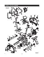
Page 18: ...PRODUCT PARTS DRAWING 18 FRONT BACK...

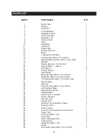
Page 19: ...Tension Spring 1 23 Idler Wheel 1 24 Bolt Hex Head M8 x 1 25 x 20mm 1 25 Nylock Nut M8 x 1 25 x 8mm thick 1 26 Thin Nylock Nut M8 x 1 25 x 6mm thick 1 27 Washer M8 8 28 Idler Arm 1 29 Bolt Hex Head M...

Page 20: ...ar 1 54 Bearing Snap Washer 1 55 Bearing Nut 2 56 Screw Round Head M4 x 16mm 6 57 Screw Round Head M4 x 30mm 3 58 Connecting Inserter 2 59 Seat Slider 1 60 Square Plug 38 x 38mm 2 61 Securing Bracket...

Page 21: ...NOTES 21...
Page 22: ...OMER SERVICE For your convenience Stamina s customer service representatives can be reached by email at customerservice staminaproducts com or by phone at 1 800 375 7520 in the U S Our customer servic...

Reviews: