background image

ASSEMBLY INSTRUCTIONS

11

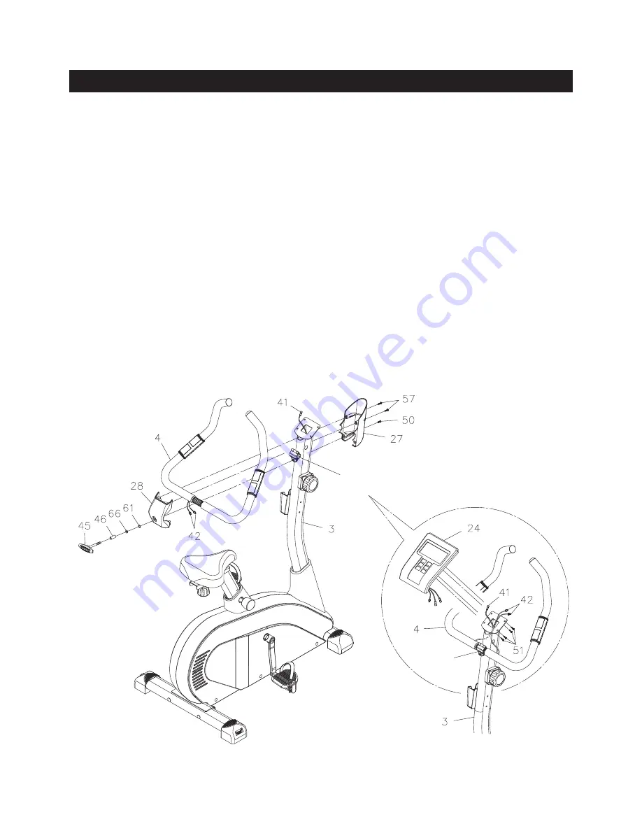
STEP 8

Place the 

HANDLEBAR(4)

 into the 

CLIP

 on the 

UPRIGHT(3).

 Refer to the detail view A. Run the 

PULSE 

SENSOR WIRES(42) 

through the holes on both sides of the 

UPRIGHT(3)

 and come out from the square 

opening on the top.

STEP 9

Install two AAA batteries into the 

METER(24),

 the batteries are not included. See page 16 for detailed 

battery installation instructions. Plug the 

CONNECTION WIRE(41)

 and 

PULSE SENSOR WIRES(42) 

into 

the 

METER(24),

 and push the excess wires back into the 

UPRIGHT(3). 

Place the 

METER(24) 

on the plate 

on the 

UPRIGHT(3)

 and secure with 

ROUND HEAD SCREWS(M5x0.8x10mm)(51).

NOTE: 

Be careful not to damage the wires when attaching the 

METER(24)

 to the 

UPRIGHT(3).

STEP 10

Attach the 

FRONT HANDLEBAR COVER(27)

 to the 

UPRIGHT(3)

 with 

ROUND HEAD SCREW(M5x0.8x16mm)

(50).

 Bolt the 

FRONT HANDLEBAR COVER(27)

 and the 

HANDLEBAR COVER(28)

 together with 

ROUND 

HEAD SCREWS(M4x20mm)(57).

 Lock the 

HANDLEBAR(4)

 in position with the 

T KNOB(45), PRESSING 

SPACER(46), LOCK WASHER(M8)(66),

 and 

SMALL WASHER(M8)(61).

Clip

Clip

A.

Summary of Contents for A150-104

Page 1: ...2 Stamina Products Inc 2012 12 Exercise can present a health risk Consult a physician before beginning any exercise program with this equipment If you feel faint or dizzy immediately discontinue use o...

Page 2: ...AT POST 5 and securely tightened 12 Each user should adjust the seat per instructions on page 13 and page 14 13 Do not attempt to adjust the seat while you are on the AVARI 2000C Upright Bike 14 Consu...

Page 3: ...ur Customer Service Department toll free number 1 800 375 7520 Monday Thursday 7 30 A M 5 00 P M Central Time Friday 8 00 A M 3 00 P M Central Time TELEPHONE CUSTOMER SERVICE Tel 1 800 375 7520 FAX CU...

Page 4: ...est standards of manufacturing and quality control there can sometimes be missing parts or incorrectly sized parts If you have any questions or problems with the parts included with your AVARI 2000C U...

Page 5: ...rovided to help identify the warning caution and notice labels on the AVARI 2000C Upright Bike Please take a moment to familiarize yourself with all of the warning caution and notice labels EQUIPMENT...

Page 6: ...re bag and make sure that you have all the following items Some hardware may be already attached to the part MILLIMETERS 0 10 20 30 40 50 60 70 80 90 100 110 120 130 140 150 0 1 2 1 1 2 2 1 2 3 1 2 4...

Page 7: ...ucts com or call us toll free at 1 800 375 7520 in the U S Our Customer Service Staff is available to assist you from 7 30 A M to 5 00 P M Central Time Monday through Thursday and 8 00 A M to 3 00 P M...

Page 8: ...EFT CRANK 9 and to attach the LEFT PEDAL STRAP 71 to the LEFT PEDAL 70 STEP 4 Refer to the Bottom View below Attach the SEAT 23 to the SEAT SLIDER 6 by inserting the connector of the SEAT SLIDER 6 int...

Page 9: ...CABLE 40 is through and extends out of the square opening in the side of the UPRIGHT 3 Connect the CONNECTION WIRE 41 to the SENSOR WIRE 39 Insert the UPRIGHT 3 into the MAIN FRAME 1 and secure with...

Page 10: ...D of the TENSION KNOB 25 to the HOOK on the end of the TENSION CABLE 40 2 Pull on the Cable of the TENSION KNOB 25 firmly so that enough cable is available to allow the METAL FITTING go through the sl...

Page 11: ...IRE 41 and PULSE SENSOR WIRES 42 into the METER 24 and push the excess wires back into the UPRIGHT 3 Place the METER 24 on the plate on the UPRIGHT 3 and secure with ROUND HEAD SCREWS M5x0 8x10mm 51 N...

Page 12: ...he bike stable Adjust as needed so that the bike sits on the floor without rocking MOVING The AVARI 2000C Upright Bike has a pair of wheels built into the LEFT and RIGHT ENDCAPS 83 84 at the front Gra...

Page 13: ...13 This monitor has extra features that will help you track your progress to keep you motivated Complete monitor instructions are on pages 15 20...

Page 14: ...on the SEAT POST 5 If your leg is too straight or if your foot cannot touch the pedal when extended at the downstroke you will need to lower the seat If your leg is bent too much you will need to rai...

Page 15: ...ing mode Press the button and hold it down for five seconds to reset all functions to zero and skip to Personal Data setting mode Press to set target values for TIME DISTANCE CALORIES and PULSE Input...

Page 16: ...ould be used only as a comparison between workouts on this unit Displays your pulse rate in beats per minute Press SET RESET buttons to input your target pulse value When you are exercising a blinking...

Page 17: ...ton to enter the values of your HEIGHT WEIGHT and AGE Press MODE button to confirm the setting and move to next item for setting NOTE You can input your personal data at any time Press the MODE button...

Page 18: ...4 6 13 14 17 18 25 25 plus General Body Fat Percentage Categories 3 BODY TYPE There are 9 BODY TYPES divided according to the FAT calculated Refer to the chart to determine what body type you are Whe...

Page 19: ...nt down from 60 seconds to zero even if you remove your hands from the Pulse Sensors If no pulse signal is available F6 0 will displayed as the pulse recovery condition D PRESET FUNCTION VALUES Stop p...

Page 20: ...ened by turning counterclockwise 3 Verify that all nuts and bolts are present and properly tightened Replace missing nuts and bolts Tighten loose nuts and bolts 4 Verify that the CAUTION LABEL 74 is i...

Page 21: ...of your maximum heart rate zone Start at the lower intensity and build up to higher intensity as you become more aerobically fit If you feel dizzy or lightheaded you should slow down or stop exercisin...

Page 22: ...cool down should include the stretches listed above and should be completed after each strength training session Lower Body Stretch Place feet shoulder width apart and lean forward Keep this position...

Page 23: ...ONE 1 YEAR AFTER DELIVERY OF THE PRODUCT TO THE PURCHASER This limited warranty is not transferable IF ANY PART OF THE PRODUCT IS NOT IN COMPLIANCE WITH THIS LIMITED WARRANTY OR ANY IMPLIED WARRANTY T...

Page 24: ...PRODUCT PARTS DRAWING 24 FRONT BACK...

Page 25: ...cer 1 21 Bearing 2 22 Tension Spring 1 23 Seat 1 24 Meter 1 25 Tension Knob 1 26 Tray 4 27 Front Handlebar Cover 1 28 Handlebar Cover 1 30 Pulse Sensor Plate 2 31 Hand Pulse Bottom Cover 2 32 Post Bus...

Page 26: ...4 59 Washer 10 5 x 20 x 2 0mm thick 1 60 Washer M4 1 61 Small Washer M8 1 62 Washer M10 5 63 Washer M8 2 64 Magnet 1 65 Arc Washer M8 2 66 Lock Washer M8 5 67 Nylock Nut M10 x 1 5 4 68 Nylock Nut M8 x...

Page 27: ...OMER SERVICE For your convenience Stamina s customer service representatives can be reached by email at customerservice staminaproducts com or by phone at 1 800 375 7520 in the U S Our customer servic...

Reviews: