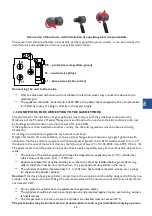
background image

- 27 -

EN

G

as .

.. P

re

ss

ur

e

R

at

ed p

ow

er

R

ed

uc

ed p

ow

er

Ig

ni

te

r

C

on

sump

tion

G

as

Sup

ply p

res

sur

e [m

bar

]

[kW

]

Ø of t

he m

ain n

ozz

le [

1/1

00 

mm]

Mai

n n

ozzl

e c

ode

Dis

tan

ce f

rom t

he a

ir 

regu

lat

or 

H[m

m]

[kW

]

Ø By-

pas

s

(m

inim

um p

osi

tion

 - 

rot

ation

s) [

1/1

00mm

]

By-

pas

s c

ode

[kW

]

Ø pilo

t noz

zle d

iam

ete

[1/1

00m

m]

Pilo

t flam

e noz

zle c

ode

Air r

egu

lat

or [

mm

]

Max

imum

 con

sumption

[k

g/

h]

[m

³/

h]

G2

0

20

9.

1

23

0

C

01

09

74

14

3.

9

11

0  r

eg *

C

011

09

9

< 0

.2

5

27

C

011

09

8

-

G2

0

 G

20

 G

27

0.

96

3

G2

0

25

9.

1

21

5

C

011

09

5

14

3.

9

11

0  r

eg *

*

C

011

09

9

< 0

.2

5

27

C

011

09

8

-

0.

96

3

G

27

20

9.

1

26

0

C

011

09

6

14

3.

9

11

0  r

eg 

***

C

011

09

9

< 0

.2

5

27

C

011

09

8

-

1.1

75

G

30

/

G

31

28

-3

0/

37

9.

1

16

0

C

01

09

12

18

3.

9

11

0  (

)

C

011

09

9

< 0

.2

5

14

C

01

09

44

-

0.

71

8

G

30

G

30

G

30

G

31

G

30

/

G

31

37

9.

1

15

0

C

01

07

94

18

3.

9

10

5 (

)

C

0111

00

< 0

.2

5

14

C

01

09

44

-

0.

71

8

G

30

/

G

31

50

9.

1

13

5

C

011

09

7

16

3.

9

95  (

)

C

0111

01

< 0

.2

5

14

C

01

09

44

-

0.

71

8

G

31

37

9.

1

16

0

C

01

09

12

18

3.

9

11

0  (

)

C

011

09

9

< 0

.2

5

14

C

01

09

44

-

0.70

7

Ta

ble

 4.

1

N

ot

e 1

:   * r

eg = b

y-

pa

ss ø

11

0 s

cr

ew a

ll t

he w

ay i

n a

nd u

ns

cr

ew 3

/4 r

ot

at

io

n - 2

70  d

eg

re

es

.

N

ot

e 2

:   * r

eg = b

y-

pa

ss ø

11

0 s

cr

ew a

ll t

he w

ay i

n a

nd u

ns

cr

ew 3

/5 r

ot

at

io

n - 2

16  d

eg

re

es

.

N

ot

e 2

:   * r

eg = b

y-

pa

ss ø

11

0 s

cr

ew a

ll t

he w

ay i

n a

nd u

ns

cr

ew 1

.5 r

ot

at

io

n - 4

50  d

eg

re

es

.

N

ot

e 4

:   (

= d

ed

ic

at

ed b

y-

pa

ss s

cr

ew

ed i

n a

ll t

he w

ay 

Summary of Contents for 9745110

Page 1: ...9745110 9745130 MAKARONIARKA GAZOWA GAS NUDELKOCHER GAS PASTA BOILER Instrukcja dla serwisu Die für den Service vorgesehene Anleitung Maintenance manual v 1 01 2018 PL DE EN 3 13 14 23 24 34 ...

Page 2: ......

Page 3: ... podłączyć do następujących mediów Zimnej wody 3 4 Gazu 1 2 Ścieków 1 Napięcie 230V 50Hz Urządzenie może być zestawiane w ciąg urządzeń W przypadku gdy urządzenie nie jest zestawione w ciągu z innymi urządzeniami tej samej linii ściany przylegające do urządzenia tył i bok powinny być wykonane z materiałów niepalnych Gniazdo zasilające powinno posiadać aktualne pomiary związane z bezpieczeństwem pr...

Page 4: ... muszą być przestrzegane przepisy obowiązujące w danym kraju Zgodnie z w w krajowymi przepisami pomieszczenie takie musi posiadać Wysokość co najmniej 2 2m oraz wentylację zapewniającą wymianę powietrza nad urządzeniami gazowymi typu restauracyjnego z odprowadzeniem spalin do kanałów spalinowych przy czym do urządzeń o mocy cieplnej większej niż 30kW należy instalować czujniki wyłączające urządzen...

Page 5: ...skami zaciskowymi Długość przewodu nie może być mniejsza niż 1 2 mb i nie może być większa niż 3 0m Butla z gazem propan butan B P musi być wyposażona w reduktor ciśnienia gazu do 3 7kPa Makaroniarka na gaz ziemny E powinna być przyłączona do instalacji gazowej wewnątrz budynku na sztywno lub przy pomocy elastycznych przewodów metalowych posiadających aktualny znak bezpieczeństwa Należy używać dwu...

Page 6: ... 25 27 C011098 0 963 G27 20 9 1 260 C011096 14 3 9 110 reg C011099 0 25 27 C011098 1 175 G30 G31 28 30 37 9 1 160 C010912 18 3 9 110 C011099 0 25 14 C010944 0 718 G30 G30 G30 G31 G30 G31 37 9 1 150 C010794 18 3 9 105 C011100 0 25 14 C010944 0 718 G30 G31 50 9 1 135 C011097 16 3 9 95 C011101 0 25 14 C010944 0 718 G31 37 9 1 160 C010912 18 3 9 110 C011099 0 25 14 C010944 0 707 Tabela 4 1 Uwaga 1 reg...

Page 7: ... 2 grupa E 20mbar gaz ziemny wysoko metanowy G20 2Lw rodzina 2 grupa LW 20mbar gaz ziemny zaazotowany G27 3B P rodzina 3 grupa B P 37mbar gaz propan butan G30 3P rodzina 3 grupa P 37mbar gaz propan G31 Moc cieplna palnika makaroniarki 400x700x850 9 1kW Rodzaj gazu Ciśnienie nominalne mbar Ciśnienie minimalne mbar Ciśnienie maksmalne mbar Średnica dyszy mm Zużycie gazu Gaz ziemny 2E G20 20 17 25 2 ...

Page 8: ...j wody 3 4 8 Podłączenie prądu 230V 50Hz 9 Termostat bezpieczeństwa 10 Wziernik pracy pilota płomienia kontrolnego 5 ADAPTACJA URZĄDZENIA NA INNY RODZAJ GAZU 1 Wymienić dysze w palniku głównym średnice dysz dla odpowiedniego gazu podane są w punkcie 4 instrukcji tabela 4 1 Dysza główna 2 Odkręcić wkręt mocujący tulejkę w korpusie palnika wysunąć lub wsunąć tulejkę w korpus do położenia zgodnego z ...

Page 9: ... umieszczony obok pokrętła na zaworze gazu Ściągnąć pokrętło z zaworu gazu aby dostać się do pokrętła by passu niekiedy niezbędny jest demon taż panela Wkręcić odpowiedni by pass zgodnie z tabela 4 1 By pass Zawór gazu 4 Wyregulować przepływ gazu na palniku pilota zmienić dyszę pilota według tabeli 4 1 po odkręceniu wkrętu 4 według tabeli 4 1 Pilot ...

Page 10: ...Tulejka dyszy 6 Dysza pilota Pilot elementy pilota UWAGA 2 Po zmiennie rodzaju gazu zasilającego urządzenie pamiętaj wymienić wszystkie dysze zgodnie z tabelą 4 1 wymianie uszczelek sprawdzeniu szczelności sprawdzić poprawność pracy palników kolor i stabilność płomienia zmianie danych na tabliczkach ...

Page 11: ...or 3 Dysza palnika glownego 4 Kolanko dyszy 5 Zawór gazu 6 Pokrętlo 7 Termostat bezpieczeństwa 8 Klamra zaworu 9 Włącznik generator 10 Włącznik zaworu wodnego 11 Elektroda 12 Dysza pilota 13 Palnik pilotowy 14 Zawór wody 15 Generator iskry 16 Elektrozawór 17 Puszka elektryczna 18 Wlewka ...

Page 12: ...rzymuje się płomień pilota Uszkodzona termopara lub niewystarczająco podgrzewana przez płomień pilota Palnik główny nie działa Ciśnienie gazu jest za niskie Dysza palnika głownego jest zapchana Zawór gazu jest uszkodzony Żółty płomień palnika glownego Zła ilość powietrza dostarczana do palnika głównego nie zbędna regulacja tulei przy dyszy palnika głównego Zabrudzony palnik główny otwory Brak iskr...

Page 13: ...d wysokiego napięcia z elektrody odkręć pilota z obudowy komory spalania odkręć elektrodę wymień elektrodę pozostałe czynności wykonaj w odwrotnej kolejności d Włącznik zapłonu odłącz przewody elektryczne z włącznika zapłonu wyjmij przełącznik z panela przedniego wymień wyłącznik pozostałe czynności wykonaj w odwrotnej kolejności e Generator iskry otwórz puszkę w której jest generator odłącz gener...

Page 14: ... werden dass es von der Frontseite aus frei zugänglich ist Hinter dem Gerät sollte sich eine aus nicht brennbaren Materialien gefertigte Wand befinden Der Nudelkocher sollte mit folgenden Anschlüssen versorgt werden Kaltes Wasser 3 4 Gas 1 2 Abwasser 1 Gleichspannung 230V 50Hz Das Gerät kann reihenweise zusammen mit anderen Geräten aufgestellt werden Wenn das Gerät nicht reihenweise zusammen mit a...

Page 15: ...Z Die für die Installation der Gasgeräte vorgesehenen Räume müssen mit den Richtlinien der Verordnung des Ministers für Raumwirtschaft und Bauwesen in der Sache der technischen Bedingungen denen die Gebäude und ihre Anordnung entsprechen sollten Gesetzblatt vom15 Juni 2002 übereinstimmen Wenn das Gerät in einem anderen Land montiert wird so müssen die in dem gegebenen Land geltenden Vorschriften b...

Page 16: ...ie Anpassung des Nudelkochers an eine andere Gasart sollte ein autorisierter Installateur durchführen Der Flüssiggas Nudelkocher sollte an eine biegsame Leitung Leitung für den Propan Butan Gas die das Sicherheitszeichen B besitzt unter der Vermittlung eines nahtlosen Stahlrohrs mit einer Länge von mindestens 50cm angeschlossen werden Die Leitung sollte an beiden Enden mit Klemmschellen vor dem Ve...

Page 17: ...963 G27 20 9 1 260 C011096 14 3 9 110 reg C011099 0 25 27 C011098 1 175 G30 G31 28 30 37 9 1 160 C010912 18 3 9 110 C011099 0 25 14 C010944 0 718 G30 G30 G30 G31 G30 G31 37 9 1 150 C010794 18 3 9 105 C011100 0 25 14 C010944 0 718 G30 G31 50 9 1 135 C011097 16 3 9 95 C011101 0 25 14 C010944 0 718 G31 37 9 1 160 C010912 18 3 9 110 C011099 0 25 14 C010944 0 707 Tabelle 4 1 Bemerkung 1 reg Bypass ø110...

Page 18: ...20 2Lw Gasfamilie 2 Gruppe L 20mbar stickstoffreiches Erdgas G27 3B P Gasfamilie 3 Gruppe B P 37 mbar Propan Butan Gas G30 3P Gasfamilie 3 Gruppe P 37 mbar Propangas G31 Die Wärmeleistung des Nudelkochers 400x700x850 9 1kW 1 der Knopf des Wasserventils 2 der Knopf des Funkengenerators 3 der Drehknopf des Gasventils 4 hinter der Tür befindet sich das Wasserablassventil 5 das Gasanschlussrohr 1 2 6 ...

Page 19: ...r Abstand H der Muffe von dem Gehäuse des Brenners 3 Den Mindestzulauf in dem Steuerungsventil regulieren man sollte die neben dem Drehknopf an dem Gasventil befindliche Schraube entsprechend ab und anschrauben Den Drehknopf vom Gasventil abnehmen um zum Drehknopf des Bypasses zu gelangen manchmal ist eine Demontage des Panels erforderlich Den entsprechenden Bypass gemäß Tabelle 4 1 anschrauben By...

Page 20: ...der Düse 6 Die Düse des Kontrollbrenners Kontrollbrenner Elemente des Kontrollbrenners ACHTUNG 2 Nach der Veränderung der Gasart daran denken Alle Düsen gemäß Tabelle 4 1 austauschen Austausch der Abdichtungen Dichtheitsprüfung Prüfung der richtigen Funktion aller Brenner der Farbe und Stabilität der Flamme Änderung der Daten in den Tabellen ...

Page 21: ...Das Kniestück der Düse 5 Gasventil 6 Drehknopf 7 Sicherheitsthermostat 8 Schelle Ventil 9 Schalter des Generators 10 Schalter des Wasserventils 11 Elektrode 12 Die Düse des Kontrollbrenners 13 Pilotflammenbrenner 14 Wasserventil 15 Funkengenerator 16 Elektroventil 17 Elektrische Dose 18 Wasserzulaufhahn ...

Page 22: ...den Hauptbrenner gelieferte Luftmenge es ist eine Regulierung der Muffen an der Düse des Hauptbren ners erforderlich Verschmutzter Hauptbrenner Öffnungen Kein Funke an den Pilotflammenbrenner Prüfen Sie ob das Gerät an das Stromnetz angeschlossen ist Prüfen Sie die Leitungsanschlüsse Beschädigte Elektrode 9 AUSTAUSCH GRUNDLEGENDER BESTANDTEILE Hauptelemente des Nudelkochers kann man nach der Entfe...

Page 23: ...nehmen den Einschalter austauschen die übrigen Maßnahmen in umgekehrter Reihenfolge ausführen e Funkengenerator den Kasten öffnen in dem sich der Generator befindet den Deckel abschrauben den Generator von den Stromleitungen abschalten den Generator austauschen die restlichen Tätigkeiten in umgekehrter Reihenfolge ausüben f Der Hauptbrenner die Verkleidung abschrauben das die Düse des Hauptbrenner...

Page 24: ...should be connected to the following services Cold water 3 4 Gas 1 2 Sewage 1 AC 230V 50Hz The device can be set up in a row of appliances If the appliance is not set up in a row with other devices of the same line the walls adjacent to the appliance rear and side should be made of non combustible materials The power outlet should have an up to date readings related to electric shock protection 3 ...

Page 25: ...e above restaurant type gas appliances with exhaust to the flues and for equipment with thermal power greater than 30kW install sensors to turn off the device in the case of the lack of chimney draft Journal of Laws 75 of 12 04 2002 item 690 174 par 10 The pasta maker should be placed in a location that is easily accessible away from combustible objects and walls The volume of the kitchen space sh...

Page 26: ...h a gas pressure reducer up to 3 7kPa Pasta makers running on natural gas E should be connected to the gas network inside the building rigidly or by means of flexible metal hoses with an updated safety mark Use a pipe union and a 1 2 seamless pipe the pasta maker has a threaded connection R 1 2 During the first installation of the device and after each change of supply another type of gas the supp...

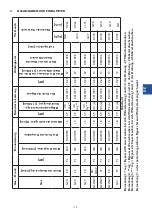
Page 27: ...27 C011098 0 963 G27 20 9 1 260 C011096 14 3 9 110 reg C011099 0 25 27 C011098 1 175 G30 G31 28 30 37 9 1 160 C010912 18 3 9 110 C011099 0 25 14 C010944 0 718 G30 G30 G30 G31 G30 G31 37 9 1 150 C010794 18 3 9 105 C011100 0 25 14 C010944 0 718 G30 G31 50 9 1 135 C011097 16 3 9 95 C011101 0 25 14 C010944 0 718 G31 37 9 1 160 C010912 18 3 9 110 C011099 0 25 14 C010944 0 707 Table 4 1 Note 1 reg by pa...

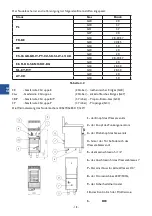
Page 28: ...PT CZ SK SI LT LV CH G20 20 G30 28 30 37 EE FI DK SE NO RO BG G20 20 G30 28 30 NL CY MT G30 28 30 AT CH G20 20 G30 50 Table 4 2 2E family 2 group E 20mbar high methane natural gas G20 2Lw family 2 group LW 20mbar nitrogen rich natural gas G27 3B P family 3 group B P 37mbar propane butane G30 3P family 3 group P 37mbar propane G31 Burner thermal power of the 400x700x850 pasta maker 9 1 kW ...

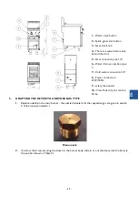
Page 29: ...8 Power connection 230V 50Hz 9 safety thermostat 10 Viewfinder of pilot control flame 5 ADAPTING THE DEVICE TO ANOTHER GAS TYPE 1 Replace nozzles in the main burner the nozzle diameters for the respective gas are given in section 4 of the manual in table 4 1 Main nozzle 2 Unscrew the screw securing the sleeve in the burner body slide in or out the sleeve into the body to the position shown in Tabl...

Page 30: ...he gas valve Remove the knob from the gas valve to get to the bypass sometimes it is necessary to dismantle the panel Screw in the appropriate by pass in accordance with Table 4 1 By pass Gas valve 4 Adjust the gas flow on the pilot burner replace the pilot nozzle according to table 4 1 after unscre wing screw 4 in accordance with table 4 1 Pilot ...

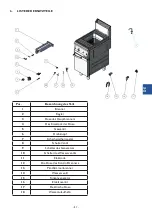
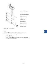
Page 31: ... cap 5 Nozzle sleeve 6 Pilot nozzle Pilot pilot components Note When changing to another type of gas remember to replace all nozzles according to Table 4 1 replace gaskets checking for leaks verify correct operation of burners flame color and stability change the data on the plates ...

Page 32: ... Main burner nozzle 4 Nozzle elbow 5 Gas valve 6 Knob 7 Safety thermostat 8 Valve brace 9 Generator switch 10 Water valve switch 11 Electrode 12 Pilot nozzle 13 Pilot burner 14 Water valve 15 Spark generator 16 Solenoid valve 17 Electrical box 18 Injection 18 Wlewka ...

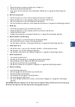
Page 33: ...ilot s flame is not retained Broken thermocouple or insufficiently heated by the pilot flame The main burner does not work Gas pressure is too low The main burner nozzle is clogged The gas valve is defective Main burner flame burns yellow Wrong amount of air supplied to the main burner requires adjustment of the sleeve at the main burner nozzle Soiled main burner holes No spark on the pilot Make s...

Page 34: ...the other steps c Electrode remove the high voltage cable from the electrode unscrew the pilot from the burner chamber housing unscrew the electrode replace the electrode reverse the other steps d Ignition switch disconnect electrical wires from the ignition switch remove the switch from the front panel replace the switch reverse the other steps e Spark generator open the box where the generator i...

Page 35: ...talgast de www stalgast de EN Tel 48 22 509 30 77 export stalgast com www stalgast eu FR ES Tel 48 22 509 30 55 export stalgast com www stalgast eu Stalgast Sp z o o Plac Konesera 9 Budynek O 03 736 Warszawa tel 22 517 15 75 fax 22 517 15 77 www stalgast com email stalgast stalgast com ...

Reviews: