background image

226834 / 972160310010

2017-06-02·BA00·III·de·02

Zubehör und Ersatzteile  

19

Media Converter FX op is / TX SC für Zone 2

Reihe 9721/13-11-xx

DE
DE
DE
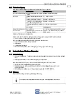
DE
DE
DE
DE
DE
DE
DE
DE
DE
DE
DE
DE
DE
DE
DE
DE
DE
DE
DE
DE
DE
DE

14

Zubehör und Ersatzteile 

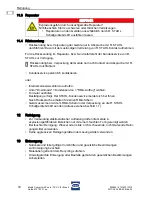
HINWEIS

Fehlfunktion oder Geräteschaden durch den Einsatz nicht originaler Bauteile.

Nichtbeachten kann Sachschaden verursachen!

• Nur Original-Zubehör und Original-Ersatzteile der R. STAHL Schaltgeräte GmbH 

verwenden.

Zubehör und Ersatzteile, siehe Datenblatt auf Homepage www.stahl-ex.com.

Summary of Contents for 9721/13-11 Series

Page 1: ... EN DE EN DE EN DE EN DE Betriebsanleitung Operating instructions Additional languages www stahl ex com DE EN Media Converter FX op is TX SC für Zone 2 Media Converter FX op is TX SC for Zone 2 Reihe 9721 13 11 Series 9721 13 11 ...

Page 2: ......

Page 3: ...DE DE DE DE DE DE DE DE DE DE DE DE DE DE DE DE DE DE DE DE DE DE DE DE DE Betriebsanleitung Additional languages www stahl ex com DE Media Converter FX op is TX SC für Zone 2 Reihe 9721 13 11 xx ...

Page 4: ...weise 5 3 1 Aufbewahrung der Betriebsanleitung 5 3 2 Sichere Verwendung 5 3 3 Umbauten und Änderungen 6 4 Funktion und Geräteaufbau 6 4 1 Funktion 6 4 2 Geräteaufbau 7 5 Technische Daten 7 6 Projektierung 10 7 Transport und Lagerung 10 8 Montage und Installation 11 8 1 Maßangaben Befestigungsmaße 12 8 2 Montage Demontage Gebrauchslage 12 8 3 Installation 15 9 Inbetriebnahme 16 10 Betrieb 16 10 1 B...

Page 5: ...r Betriebsanleitung ID Nr 226834 972160310010 Publikationsnummer 2017 06 02 BA00 III de 02 Die Originalbetriebsanleitung ist die englische Ausgabe Diese ist rechtsverbindlich in allen juristischen Angelegenheiten 1 3 Weitere Dokumente Datenblatt Weitere Sprachen siehe www stahl ex com 1 4 Konformität zu Normen und Bestimmungen Siehe Zertifikate und EU Konformitätserklärung www stahl ex com Das Ger...

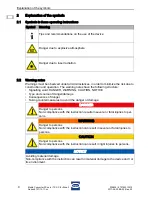
Page 6: ...hadens Folgen der Gefahr Ergreifen von Gegenmaßnahmen zum Vermeiden der Gefahr bzw des Schadens Symbol Bedeutung Tipps und Empfehlungen zum Gebrauch des Geräts Gefahr durch explosionsfähige Atmosphäre Gefahr durch Laserstrahlung GEFAHR Gefahren für Personen Nichtbeachtung der Anweisung führt zu schweren oder tödlichen Verletzun gen bei Personen WARNUNG Gefahren für Personen Nichtbeachtung der Anwe...

Page 7: ...fallverhütungsvorschriften beachten Bei Installation und im Betrieb die Angaben Kennwerte und Bemessungsbetriebs bedingungen auf Typ und Datenschildern sowie die Hinweisschilder am Gerät beachten Vor Installation sicherstellen dass das Gerät unbeschädigt ist Das Gerät ist für den Einsatz in gasexplosionsgefährdeten Bereichen der Zone 2 in staubexplosionsgefährdeten Bereichen der Zone 22 sowie auch...

Page 8: ...enen zur Umsetzung eines elektrischen Ethernet Netzwerks TX auf Lichtwellenleiter FX Der Lichtwellenleiter wird zum Betrieb in explosionsgefährdeten Bereichen der Zonen 0 1 und 2 in der Zündschutzart op is IEC EN 60079 28 ausgeführt Hiermit sind konventionelle Lichtwellenleiter Kabel auch in explosionsgefährdeten Bereichen einsetzbar und dürfen im Betrieb gesteckt und getrennt werden hot swap GEFA...

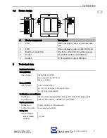
Page 9: ... Ethernet 5 Buchse RJ45 Buchse für Kupfer Ethernet Explosionsschutz Global IECEx Gas und Staub IECEx TUR 13 0014X Ex nA op is T6 Ga IIC T4 Gc Ex op is Da IIIC Europa ATEX Gas und Staub TÜV 13 ATEX 7316 X E II 3 1 G Ex nA op is T6 Ga IIC T4 Gc E II 1 D Ex op is Da IIIC Bescheinigungen und Zertifikate Bescheinigungen IECEx ATEX Kasachstan TR Russland TR USA cFM Weißrussland TR Schiffszertifikate ABS...

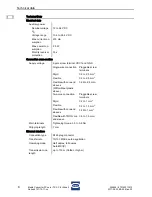
Page 10: ...gsspan nung 2 polige Schraubklemme VDC1 und GND Hauptklemmen Anzugsmoment 0 5 0 6 Nm Abisolierlänge 7 mm Schnittstelle Ethernet Anschlussart RJ45 Steckverbinder Übertragungsrate 10 100 Mbit s Auto Negotiation Betriebsart Halbduplex Volllduplex Auto MDI X Übertragungslänge bis 100 m Cat5e oder besser Anschluss einadrig steckbare Schraubklemmen starr 0 2 2 5 mm2 flexibel 0 2 2 5 mm2 flexibel mit Ade...

Page 11: ...n 3 5 ps nm km 800 500 MHz km Umgebungsbedingungen Umgebungs temperatur 30 75 C Lagertemperatur 40 80 C Relative Feuchte 95 ohne Betauung Elektromagnetische Verträglichkeit geprüft nach folgenden Normen und Vorschriften für den Einsatz im industriellen Bereich IEC EN 61326 1 Verwendung in Höhe 2000 m Mechanische Daten Einbaubedingungen Montageart auf 35 mm DIN Schiene NS 35 15 oder Wandmontage Ein...

Page 12: ...nische Daten zur Verfügung stellen 7 Transport und Lagerung Gerät nur in Originalverpackung transportieren und lagern Gerät trocken keine Betauung und erschütterungsfrei lagern Gerät nicht stürzen GEFAHR Explosionsgefahr durch zu hohe Temperatur im Schaltschrank Nichtbeachten führt zu schweren oder tödlichen Verletzungen Schaltschrank so aufbauen und einrichten dass er immer innerhalb des zulässig...

Page 13: ...in Zone 2 und im sicheren Bereich ist ein Gehäuse mit mindestens IP54 erforderlich Bei Einsatz in Zone 22 ist ein Gehäuse mit mindestens IP64 erforderlich GEFAHR Explosionsgefahr durch falsche Installation des Geräts Nichtbeachten führt zu schweren oder tödlichen Verletzungen Installation strikt nach Anleitung und unter Berücksichtigung der nationalen Sicherheits und Unfallverhütungsvorschriften d...

Page 14: ...ntage horizontal auf Hutschiene Maßzeichnungen alle Maße in mm Zoll Änderungen vorbehalten 16309E00 9721 13 17549E00 17550E00 Vormontierten Montage Clip 3 von unten an die Hutschiene 1 ansetzen Die Feder 2 muss dabei hinter der Hutschiene liegen Gerät kräftig nach oben drücken und auf die Hutschiene einrasten Vergewissern dass das Gerät sicher montiert ist X 6 2 0 36 80 3 15 25 0 98 32 1 26 30 1 8...

Page 15: ...elassen 16513E00 Vormontierten Montage Clip durch Vertikal Montage Clip ersetzen Zur Fixierung dieselben Schrauben verwenden Vertikal Montage Clip von unten an die Hutschiene ansetzen Gerät mit etwas Druck nach unten drücken und gleichzeitig auf die Hutschiene aufrasten Siehe auch Montage horizontal auf Hutschiene Vergewissern dass das Gerät sicher montiert ist 16512E00 Vormontierten Montage Clip ...

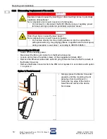
Page 16: ... Option 1 Frontale Entnahme GEFAHR Explosionsgefahr durch Stecken oder Trennen von Leitungen in explosionsfähiger Atmosphäre Nichtbeachten führt zu schweren oder tödlichen Verletzungen RJ45 Ethernet Stecker oder Hilfsenergie Klemmen während des Betriebs in explosionsgefährdeten Bereichen nicht stecken und nicht trennen GEFAHR Augenverletzung durch Laserstrahl Nichtbeachten führt zu schweren Verlet...

Page 17: ...J45 Steckverbinder an die Buchse des Geräts anschließen 17553E00 Media Converter je nach Platzverhältnissen von der Hutschiene herausschieben Bei Betrieb unter erschwerten Bedingungen wie insbesondere auf Schiffen sind zusätzliche Maßnahmen zur korrekten Installation je nach Einsatzort zu treffen Weitere Informationen und Anweisungen hierzu erhalten Sie gerne auf Anfrage von Ihrem zuständigen Vert...

Page 18: ...triebnahme die Hilfsenergieversorgung einschalten 10 2 Anzeige Entsprechende LEDs am Gerät zeigen den Betriebszustand des Geräts und die Leitungsfehlerzustände an siehe auch Kapitel Funktion und Geräteaufbau GEFAHR Explosionsgefahr durch fehlerhafte Installation Nichtbeachten führt zu schweren oder tödlichen Verletzungen Gerät vor der Inbetriebnahme auf korrekte Installation prüfen Nationale Besti...

Page 19: ...ungen anpassen Bei der Instandhaltung des Geräts mindestens folgende Punkte prüfen fester Sitz der untergeklemmten Leitungen Rissbildung und andere sichtbare Schäden am Gerätegehäuse und oder Schutzgehäuse Einhaltung der zulässigen Temperaturen gemäß IEC EN 60079 11 2 Wartung Das Gerät benötigt keine regelmäßige Wartung Fehler Fehlerursache Fehlerbehebung LED leuchtet oder blinkt Normaler Anschlus...

Page 20: ...RMA Schein in der Verpackung an die R STAHL Schaltgeräte GmbH senden Adresse siehe Abschnitt 1 1 12 Reinigung Zur Vermeidung elektrostatischer Aufladung dürfen die Geräte in explosionsgefährdeten Bereichen nur mit einem feuchten Tuch gereinigt werden Bei feuchter Reinigung Wasser oder milde nicht scheuernde nicht kratzende Reini gungsmittel verwenden Keine aggressiven Reinigungsmittel oder Lösungs...

Page 21: ...DE DE DE DE DE DE DE DE DE DE DE DE DE DE DE DE DE 14 Zubehör und Ersatzteile HINWEIS Fehlfunktion oder Geräteschaden durch den Einsatz nicht originaler Bauteile Nichtbeachten kann Sachschaden verursachen Nur Original Zubehör und Original Ersatzteile der R STAHL Schaltgeräte GmbH verwenden Zubehör und Ersatzteile siehe Datenblatt auf Homepage www stahl ex com ...

Page 22: ......

Page 23: ...EN EN EN EN EN EN EN EN EN EN EN EN EN EN EN EN EN EN EN EN EN EN EN EN EN Operating instructions Additional languages www stahl ex com EN Media Converter FX op is TX SC for Zone 2 Series 9721 13 11 xx ...

Page 24: ... 3 Safety notes 5 3 1 Operating instructions storage 5 3 2 Safe use 5 3 3 Modifications and alterations 6 4 Function and device design 6 4 1 Function 6 4 2 Device design 7 5 Technical data 7 6 Engineering 10 7 Transport and storage 10 8 Mounting and installation 11 8 1 Dimensions fastening dimensions 12 8 2 Mounting dismounting operating position 12 8 3 Installation 15 9 Commissioning 16 10 Operat...

Page 25: ...de 1 2 Information regarding the operating instructions ID No 226834 972160310010 Publication Code 2017 06 02 BA00 III en 02 The original instructions are the English edition They are legally binding in all legal affairs 1 3 Further documents Data sheet For further languages see www stahl ex com 1 4 Conformity with standards and regulations See certificates and EU Declaration of Conformity www sta...

Page 26: ... NOTICE Type and source of danger damage Consequences of danger Taking countermeasures to avoid the danger or damage Symbol Meaning Tips and recommendations on the use of the device Danger due to explosive atmosphere Danger due to laser radiation DANGER Danger to persons Non compliance with the instruction results in severe or fatal injuries to per sons WARNING Danger to persons Non compliance wit...

Page 27: ...revention regulations During installation and operation observe the information characteristic values and rated operating conditions on the type plates and data plates and information signs located on the device Before installation make sure that the device is not damaged The device is approved for use in areas of Zone 2 with potentially explosive gas in ar eas of Zone 22 with potentially explosiv...

Page 28: ...erters 9721 are used for the implementation of an electrical Ethernet net work TX to fibre optic FX The fibre optic is used for operation in potentially explosive areas of Zone 0 1 and 2 with the type of protection op is IEC EN 60079 28 Therefore conventional fibre optic cables can also be used in hazardous areas and may be connect ed and disconnected during operation hot swap DANGER Explosion haz...

Page 29: ...4 Socket SC socket for fibre optic Ethernet 5 Socket RJ45 socket for copper Ethernet Explosion Protection Global IECEx Gas and dust IECEx TUR 13 0014X Ex nA op is T6 Ga IIC T4 Gc Ex op is Da IIIC Europe ATEX Gas and dust TÜV 13 ATEX 7316 X E II 3 1 G Ex nA op is T6 Ga IIC T4 Gc E II 1 D Ex op is Da IIIC Certifications and certificates Certificates IECEx ATEX Kazakhstan TR Russia TR USA cFM Belarus...

Page 30: ...e screw terminal VDC1 and GND Main terminals Tightening torque 0 5 to 0 6 Nm Stripping length 7 mm Ethernet interface Connection type RJ45 plug connector Transfer rate 10 100 Mbit s auto negotiation Operating mode Half duplex full duplex Auto MDI X Transmission line length up to 100 m Cat5e or higher Single wire connection Pluggable screw terminals Rigid 0 2 to 2 5 mm2 Flexible 0 2 to 2 5 mm2 Flex...

Page 31: ...z km Ambient conditions Ambient temperature 30 75 C Storage temperature 40 to 80 C Relative humidity 95 without condensation Electromagnetic compatibility Tested in accordance with the following standards and regulations for use in the industrial area IEC EN 61326 1 Use at the height of 2 000 m Mechanical data Installation condi tions Mounting type On the 35 mm DIN rail NS 35 15 or wall mounting M...

Page 32: ...a Chapter 7 Transport and storage Transport and store the device only in the original packaging Store the device in a dry place no condensation and vibration free Do not drop the device DANGER Explosion hazard due to too high temperature in the cabinet Non compliance results in severe or fatal injuries Install and adjust the cabinet in such a way that it is always operated within the permissible t...

Page 33: ...at least an IP54 protection rating is required for use in Zone 2 and in safe areas Enclosure with at least an IP64 protection rating is required for use in Zone 22 DANGER Explosion hazard due to incorrect installation of the device Non compliance results in severe or fatal injuries Carry out installation strictly according to the instructions and national safety and accident prevention regulations...

Page 34: ...izontal mounting on DIN rail Dimensional drawings all dimensions in mm inches Subject to alterations 16309E00 9721 13 17549E00 17550E00 Attach the pre assembled mounting clip 3 to the DIN rail 1 from below The spring 2 must be located behind the DIN rail Strongly press the device upwards and snap it into place on the DIN rail Make sure the device is securely installed X 6 2 0 36 80 3 15 25 0 98 32...

Page 35: ...ot permitted on ships 16513E00 Replace the pre assembled mounting clip with a vertical mounting clip Use the same screws for fastening Attach the vertical mounting clip to the DIN rail from below Press down the device with some force and simultaneously lock it on to the DIN rail See also Horizontal mounting on DIN rail Make sure the device is securely installed 16512E00 Remove pre assembled mounti...

Page 36: ...ption 1 or option 2 Option 1 Frontal removal DANGER Explosion hazard caused by inserting or disconnecting cables in potentially explosive atmospheres Non compliance can result in severe or fatal injuries Do not insert or disconnect the RJ45 Ethernet plug or auxiliary power terminals during operation in potentially explosive areas DANGER Risk of eye injury caused by laser beam Non compliance can re...

Page 37: ...J45 plug connector to the socket of the device 17553E00 Slide the Media Converter out from the DIN rail depending on the space available Operation under difficult conditions such as in particular on ships requires additional measures to be taken for correct installation depending on the place of use Further information and instructions on this can be obtained from your regional sales contact on re...

Page 38: ...ioning chapter switch on the auxiliary power source 10 2 Indication The corresponding LEDs on the device indicate the operating conditions of the device and the line fault states also refer to chapter Function and Device Design DANGER Explosion hazard due to incorrect installation Non compliance results in severe or fatal injuries Check the device for proper installation before commissioning Compl...

Page 39: ...following points should be checked during the maintenance of the device Whether or not the clamping screws holding the electric cables have been firmly tight ened If the device enclosure and or protective enclosure have cracks or other visible signs of damage The compliance with the permissible temperatures according to IEC EN 60079 11 2 Maintenance The device does not require regular maintenance ...

Page 40: ...mer service Send the device along with the RMA slip in the packaging to R STAHL Schaltgeräte GmbH refer to Section 1 1 for the address 12 Cleaning To avoid electrostatic charging the devices located in potentially explosive areas may only be cleaned using a damp cloth When cleaning with a damp cloth use water or mild non abrasive non scratching cleaning agents Do not use aggressive detergents or s...

Page 41: ...N EN EN EN EN EN EN EN EN EN EN EN EN EN EN EN EN 14 Accessories and Spare parts NOTICE Malfunction or damage to the device due to the use of non original components Non compliance can result in material damage Use only original accessories and spare parts from R STAHL Schaltgeräte GmbH For accessories and spare parts see data sheet on our homepage www stahl ex com ...

Page 42: ...mode port 6 Power supply VDC1 or VDC2 Nominal voltage 24 V DC Voltage range 12 30 V DC Nominal power consumption 6 4 W 12 V Safety data for the optical interface Maximum radiated optical power 15 mW Notes 1 Installation should be in accordance with Article 504 505 of the National Electrical Code ANSI NFPA 70 and ANSI ISA RP 12 06 01 2 Installation in Canada should be in accordance with the Canadia...

Page 43: ......

Reviews: