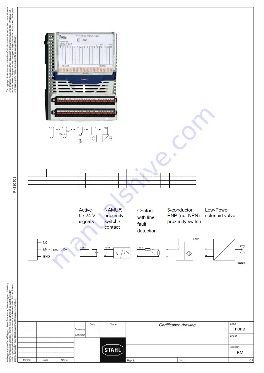
Digital Input Output Module,
Type 9471/35-16-11
9471 6 031 001 1
1 of 1
2018
22.05. Bagusch
Kaiser
Nonhazardous (Unclassified),
Class I, II, III, Division 2, Group A-D
or Class I, Zone 2, Group IIC/IIB
Hazardous (Classified) Locations
Approved NAMUR proximity switches,
optocouplers, low power solenoid valves
The Digital Input Output Module Type 9471/35-16-11 is designed to
receive up to 16 discrete input signals from dry contacts and NAMUR
proximity sensors etc. and transfer them to the IS1 CPU & Power
Module. It is also possible to drive low power solenoid valves.
The module is for use in Nonhazardous (Unclassified), Class I,
Division 2, Group A-D or Class I, Zone 2, Group IIC Hazardous
(Classified) Locations according to NEC Article 501/504/505 or
Canadian Electrical Code, CSA C22.
The system internal circuits are safely galvanically isolated from all
input circuits up to a peak voltage of 375 V.
Maximum Safety Voltage for the Input circuits: U
max
= 253 V AC
Notes:
1.
Suitable separation must be maintained between input circuits
connected to nonincendive circuits, AEx/Ex nA circuits and the
I.S. input circuits of other I/O modules of the IS1 resp. IS1+
system. Use partition (SAP No. 162740 or 220101) for separation
from I/O modules with I.S. circuits. Do not carry out work at the
terminals without the partition plate in place.
2.
Electrical Apparatus connected to an intrinsically safe system
must not use or generate voltages > 253 V (U
max
)
3.
Do not disconnect nonincendive circuits or AEx/Ex nA circuits
unless area is known to be non hazardous. Mechanically secure
the terminal blocks with the screws provided, to prevent from
being detached unintentionally.
4.
Only use BusRail extension Type 9494/L1-V* fitted aside the
module. Do not mount the module fitted aside BusRail Begin or
BusRail Begin types 9494/A2-B0 or 9494/A2-E0.
5.
For Installation in Division 2 or Zone 2 see Certification drawing
for IS1 resp. IS1+ Remote I/O System No. 9400 6 031 004 1 or
9400 6 031 006 1 as part of the documentation of the CPU &
Power Modules.
Wiring Legend
X1 and X2 connection allocation
Terminal
X1
X2
Function
Channel
0
1
2
3
4
5
6
7
8
9
10
11
12
13
14
15
Not connected (NC)
1
4
7
10
13
16
19
22
25
28
31
34
37
40
43
46
Signal Input (E)
2
5
8
11
14
17
20
23
26
29
32
35
38
41
44
47
Ground (GND)
3
6
9
12
15
18
21
24
27
30
33
36
39
42
45
48
The GND lines are internally connected. Parallel interconnection of outputs is not permissible.
For 3-wire proximity switches only PNP versions shall be connected, no NPN.
Connection Diagram for Field Devices at X1 and X2:
X2
X1


