background image

Parameterization and Commissioning

10

262225 / 8402610300

2018-08-07·BA00·III·en·02

EN
EN
EN
EN
EN
EN
EN
EN
EN
EN
EN
EN
EN
EN
EN
EN
EN
EN
EN
EN
EN
EN
EN
EN
EN

Ammeters and voltmeters

Series 8402/6, Series 8403/6, Series 8404/6, 

Series 8405/6, Series 8406/6, Series 8407/6

6

Parameterization and Commissioning

6.1

Parameterizations

After the installation, the following settings can be configured (if necessary):

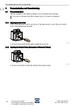
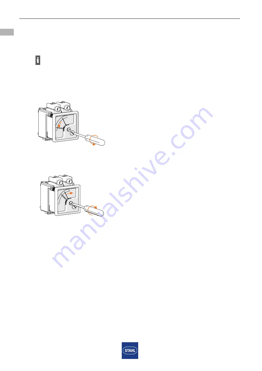
6.1.1 Adjusting the Zero Point

A zero point adjustment can be carried out, if the black pointer is not in the zero position  

at 0 A, after installing the ammeter.

19963E00

Use the screw at the bottom right to adjust the zero point.

6.1.2 Adjusting the Desired Value (Comparison of Measured Values)

19964E00

Use the red pointer to adjust the desired value (upper screw).

The scale of ammeters with direct display may by no means be replaced!

0

Summary of Contents for 8402/6 Series

Page 1: ... DE DE DE DE DE DE DE DE DE DE DE DE DE Betriebsanleitung Additional languages www r stahl com DE Strom und Spannungsmesser Reihe 8402 6 Reihe 8403 6 Reihe 8404 6 Reihe 8405 6 Reihe 8406 6 Reihe 8407 6 Für künftige Verwendung aufbewahren ...

Page 2: ...n der Betriebsanleitung 4 2 2 Symbole am Gerät 4 3 Sicherheit 5 3 1 Bestimmungsgemäße Verwendung 5 3 2 Qualifikation des Personals 5 3 3 Restrisiken 6 4 Transport und Lagerung 7 5 Montage und Installation 7 5 1 Montage 7 5 2 Installation 9 6 Parametrierung und Inbetriebnahme 10 6 1 Parametrierungen 10 6 2 Inbetriebnahme 12 7 Instandhaltung Wartung Reparatur 12 7 1 Instandhaltung 12 7 2 Wartung 12 ...

Page 3: ...hren Betriebsanleitung dem Bedien und Wartungspersonal jederzeit zugänglich machen Betriebsanleitung an jeden folgenden Besitzer oder Benutzer des Geräts weitergeben Betriebsanleitung bei jeder von R STAHL erhaltenen Ergänzung aktualisieren ID Nr 262225 8402610300 Publikationsnummer 2018 08 07 BA00 III de 02 Die Originalbetriebsanleitung ist die deutsche Ausgabe Diese ist rechtsverbindlich in alle...

Page 4: ...rensituation die bei Nichtbeachtung der Sicherheitsmaßnahmen zu schweren Verletzungen führen kann VORSICHT Gefahrensituation die bei Nichtbeachtung der Sicherheitsmaßnahmen zu leichten Verletzungen führen kann HINWEIS Gefahrensituation die bei Nichtbeachtung der Sicherheitsmaßnahmen zu Sachschäden führen kann Symbol Bedeutung 05594E00 CE Kennzeichnung gemäß aktuell gültiger Richtlinie 16338E00 Ben...

Page 5: ...atz in explosionsgefährdeten Bereichen der Zonen 1 und 21 und im sicheren Bereich zugelassen Voraussetzung für ihre Verwendung im explosionsgefährdeten Bereich ist ihr Einbau in ein Gehäuse oder einen Schrank mit einer Schutzart entsprechend IEC EN 60079 0 und Schutzklasse IP54 oder höher 3 2 Qualifikation des Personals Für die in dieser Betriebsanleitung beschriebenen Tätigkeiten ist eine entspre...

Page 6: ... Gerät in Originalverpackung trocken keine Betauung in stabiler Lage und sicher vor Erschütterungen lagern Gerät und weitere Systemkomponenten während der Montage nicht beschädigen Unsachgemäße Montage Installation Inbetriebnahme Instandhaltung oder Reinigung Grundlegende Arbeiten wie Montage Inbetriebnahme Instandhaltung oder Reinigung des Geräts dürfen nur nach gültigen nationalen Bestimmungen d...

Page 7: ...port und Lagerung Gerät sorgfältig und unter Beachtung der Sicherheitshinweise siehe Kapitel Sicherheit transportieren und lagern 5 Montage und Installation 5 1 Montage Gerät sorgfältig und nur unter Beachtung der Sicherheitshinweise siehe Kapitel Sicherheit montieren Folgende Einbaubedingungen und Montageanweisungen genau durchlesen und exakt befolgen 5 1 1 Gebrauchslage 19962E00 Strom und Spannu...

Page 8: ... Montage auf Montageplatte 19971E00 Gerät durch die seitlichen Befestigungslaschen mit zwei Schrauben auf Montageplatte montieren 5 1 3 Montage auf Montageplatte für Hutschienen Montage 19978E00 Montageplatte 2 mit den Schrauben 1 an den Strom und Spannungsmesser 3 schrauben Anzugsdrehmoment 1 2 Nm 5 1 4 Montage auf Schiene 19972E00 Gerät an einer Seite auf Tragschiene TS35 einhaken und auf der an...

Page 9: ...emmen und stromführenden Leitern sowie maximalen Strombelastung Sicherstellen dass die Länge eines Leiters von der Verschraubung bis zur Klemmstelle die Länge der Gehäusediagonale nicht überschreitet Bei Betrieb unter erschwerten Bedingungen wie insbesondere auf Schiffen sind zusätzliche Maßnahmen zur korrekten Installation je nach Einsatzort zu treffen Weitere Informationen und Anweisungen hierzu...

Page 10: ...n bei Bedarf folgende Einstellungen vorgenommen werden 6 1 1 Nullpunkt einstellen Für den Fall dass der schwarze Zeiger nach dem Einbau des Strom oder Spannungsmessers bei 0 A nicht mehr in der Nullstellung steht kann eine Nullpunkteinstellung vorgenommen werden 19963E00 Den Nullpunkt mit Hilfe der Schraube unten rechts justieren 6 1 2 Sollwert einstellen Messwertvergleich 19964E00 Sollwert obere ...

Page 11: ... 8403 6 Reihe 8404 6 Reihe 8405 6 Reihe 8406 6 Reihe 8407 6 6 1 3 Austausch der Skala 19974E00 Schieber am Gehäuse herunter schieben 19975E00 Skalenschild mit Hilfe eines Schraubendrehers vorsichtig aus der Öffnung herausziehen Dabei Zeiger nicht verbiegen 19976E00 Neues Skalenschild vorsichtig einschieben Dabei Zeiger nicht verbiegen 19977E00 Schieber am Gehäuse hochschieben bis er wieder einrast...

Page 12: ...are Schäden am Gerätegehäuse und oder Schutzgehäuse Einhaltung der zulässigen Temperaturen festen Sitz der Befestigungen 7 2 Wartung Gerät gemäß den geltenden nationalen Bestimmungen und den Sicherheitshinweisen dieser Betriebsanleitung Kapitel Sicherheit warten 7 3 Reparatur Reparaturen am Gerät nur mit Original Ersatzteilen und nach Absprache mit R STAHL durchführen 8 Rücksendung Rücksendung bzw...

Page 13: ... Wasser oder milde nicht scheuernde nicht kratzende Reinigungsmittel verwenden Keine aggressiven Reinigungsmittel oder Lösungsmittel verwenden Gerät nie mit starkem Wasserstrahl z B mit einem Hochdruckreiniger reinigen 10 Entsorgung Nationale und lokal gültige Vorschriften und gesetzliche Bestimmungen zur Entsorgung beachten Materialien getrennt dem Recycling zuführen Umweltgerechte Entsorgung all...

Page 14: ...eihe 8403 6 10 2 8403 6 15 2 8404 6 8405 6 10 2 8405 6 15 2 Ex eb mb IIC Gb Reihe 8406 6 020 2 8407 6 2 Ex eb ib mb IIC Gb Reihe 8403 6 8405 6 Ex eb I Mb Reihe 8403 6 10 2 8403 6 15 2 8404 6 8405 6 10 2 8405 6 15 2 Ex eb mb I Mb Reihe 8406 6 020 2 8407 6 2 Ex eb ib mb I Mb Reihe 8402 6 SIQ 18 ATEX 018 X Reihe 8403 6 8405 6 SIQ 17 ATEX 192 U Reihe 8404 6 SIQ 18 ATEX 016 U Reihe 8406 6 8407 6 SIQ 18...

Page 15: ...riante 2 5A 125 A 50xIN 1 s Variante 4 A 200 A 50xIN 1 s Variante 5 A 250 A 50xIN 1 s Variante 10 A 500 A 50xIN 1 s Variante 15 A 750 A 50xIN 1 s Variante 25 A 750 A 30xIN 1 s Variante 1 A 50 A 50xIN 1 s Variante 4 A 200 A 50xIN 1 s Variante 5 A 250 A 50xIN 1 s Variante 10 A 500 A 50xIN 1 s Variante 15 A 450 A 30xIN 1 s Variante 20 mA 200 mA 10xIN 5 s Variante 20 mA 200 mA 10xIN 5 s Spannung bei k...

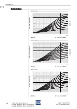
Page 16: ... Reihe 8406 6 Reihe 8407 6 Verschmutzungsgrad 3 Verwendung in Höhe 2000 m Umgebungsbedingungen Umgebungstemperatur 40 70 C Temperaturklasse T6 40 C Tamb 40 C T5 40 C Tamb 55 C T4 40 C Tamb 70 C Temperaturklasse in Abhängigkeit des Anlaufstromes Überlast Zeit Technische Daten Absolut Temperatur 20256E00 fx Überlast Zeit in s A max Anlaufzeit Absolut Temperatur 20257E00 fx Überlast Zeit in s A max A...

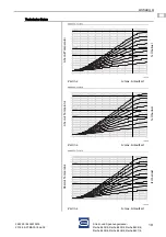
Page 17: ...DE DE Strom und Spannungsmesser Reihe 8402 6 Reihe 8403 6 Reihe 8404 6 Reihe 8405 6 Reihe 8406 6 Reihe 8407 6 Technische Daten Absolut Temperatur 20258E00 fx Überlast Zeit in s A max Anlaufzeit Absolut Temperatur 20259E00 fx Überlast Zeit in s A max Anlaufzeit Absolut Temperatur 20260E00 fx Überlast Zeit in s A max Anlaufzeit ...

Page 18: ...DE DE Strom und Spannungsmesser Reihe 8402 6 Reihe 8403 6 Reihe 8404 6 Reihe 8405 6 Reihe 8406 6 Reihe 8407 6 Technische Daten Absolut Temperatur 20261E00 fx Überlast Zeit in s A max Anlaufzeit Absolut Temperatur 20249E00 fx Überlast Zeit in s A max Anlaufzeit Absolut Temperatur 20250E00 fx Überlast Zeit in s A max Anlaufzeit ...

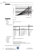
Page 19: ...DE DE Strom und Spannungsmesser Reihe 8402 6 Reihe 8403 6 Reihe 8404 6 Reihe 8405 6 Reihe 8406 6 Reihe 8407 6 Technische Daten Absolut Temperatur 20251E00 fx Überlast Zeit in s A max Anlaufzeit Absolut Temperatur 20252E00 fx Überlast Zeit in s A max Anlaufzeit Absolut Temperatur 25253E00 fx Überlast Zeit in s A max Anlaufzeit ...

Page 20: ...nge 10 mm Klemmenart Schraubanschluss Zugbügelklemme Genauigkeit 2 5 Befestigung Variante 1 Aufrasten auf Hutschiene TS35 Variante 2 Montage mit 2 Schrauben auf Montageplatte Montagezusatz Art Nr 130954 bei Reihe 8405 6 und 8406 6 im Lieferumfang enthalten Technische Daten Absolut Temperatur 20254E00 fx Überlast Zeit in s A max Anlaufzeit für Messbereiche Reihe 8402 8404 8406 8407 eindrähtig flexi...

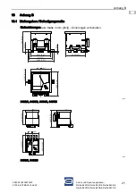
Page 21: ...ihe 8403 6 Reihe 8404 6 Reihe 8405 6 Reihe 8406 6 Reihe 8407 6 13 Anhang B 13 1 Maßangaben Befestigungsmaße Maßzeichnungen alle Maße in mm Zoll Änderungen vorbehalten 19960E00 8402 6 8403 6 8404 6 8407 6 19961E00 8405 6 8406 6 8 0 31 71 20 2 80 66 80 2 63 80 3 15 88 80 3 50 3 0 12 66 50 2 62 83 50 3 29 72 2 83 Ø Ø 4 50 0 18 56 70 2 23 60 2 36 51 50 2 03 59 50 2 34 48 1 89 ...

Page 22: ......

Page 23: ... EN EN EN EN EN EN EN EN EN EN EN EN EN EN Operating instructions Additional languages www r stahl com EN Ammeters and voltmeters Series 8402 6 Series 8403 6 Series 8404 6 Series 8405 6 Series 8406 6 Series 8407 6 Save for future use ...

Page 24: ...ymbols in these Operating Instructions 4 2 2 Symbols on the Device 4 3 Safety 5 3 1 Intended Use 5 3 2 Personnel Qualification 5 3 3 Residual Risks 6 4 Transport and Storage 7 5 Mounting and Installation 7 5 1 Assembly 7 5 2 Installation 9 6 Parameterization and Commissioning 10 6 1 Parameterizations 10 6 2 Commissioning 12 7 Maintenance Overhaul Repair 12 7 1 Maintenance 12 7 2 Overhaul 12 7 3 Re...

Page 25: ...evice Make the operating instructions accessible to operating and maintenance personnel at all times Pass the operating instructions on to each subsequent owner or user of the device Update the operating instructions every time you receive an amendment to them from R STAHL ID No 262225 8402610300 Publication Code 2018 08 07 BA00 III en 02 The original instructions are the German edition They are l...

Page 26: ...d with WARNING Dangerous situation which can result in severe injuries if the safety measures are not complied with CAUTION Dangerous situation which can result in minor injuries if the safety measures are not complied with NOTICE Dangerous situation which can result in material damage if the safety measures are not complied with Symbol Meaning 05594E00 CE marking in accordance with the current ap...

Page 27: ... voltage values They are approved for use in hazardous areas of Zones 1 and 21 and in safe areas In order to be used in hazardous areas they must be installed in an enclosure or cabinet with a degree of protection corresponding to IEC EN 60079 0 and class of IP54 or higher 3 2 Personnel Qualification Qualified specialist personnel are required to perform the activities described in these operating...

Page 28: ...s stable and protected against the effects of vibrations and knocks Do not damage the device and other system components during mounting Improper mounting commissioning maintenance or cleaning Basic work such as mounting commissioning maintenance or cleaning of the device must be performed only in accordance with the applicable national regulations of the country of use and only by qualified perso...

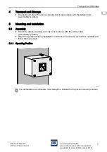
Page 29: ...torage Transport and store the device carefully and in accordance with the safety notes see Safety section 5 Mounting and Installation 5 1 Assembly Mount the device carefully and only in accordance with the safety notes see Safety section Read through the following installation conditions and assembly instructions carefully and follow them precisely 5 1 1 Operating Position 19962E00 The ammeters a...

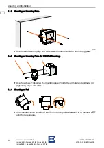
Page 30: ...7 6 5 1 2 Mounting on Mounting Plate 19971E00 Use the side fastening clips with two screws to mount the device on mounting plate 5 1 3 Mounting on Mounting Plate for DIN Rail Mounting 19978E00 Use the screws 1 to screw the mounting plate 2 onto the ammeter and voltmeter 3 tightening torque of 1 2 Nm 5 1 4 Mounting on Rail 19972E00 Hook the device into one side of the TS35 mounting rail and swivel ...

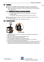
Page 31: ...th all possible terminals and live conductors and the maximum current load has been reached ensure that the length of a conductor from the screw connection to the terminal point does not exceed the diagonal planes of the enclosure Operation under difficult conditions in particular on ships requires additional measures to be taken for correct installation depending on the operating location Further...

Page 32: ...izations After the installation the following settings can be configured if necessary 6 1 1 Adjusting the Zero Point A zero point adjustment can be carried out if the black pointer is not in the zero position at 0 A after installing the ammeter 19963E00 Use the screw at the bottom right to adjust the zero point 6 1 2 Adjusting the Desired Value Comparison of Measured Values 19964E00 Use the red po...

Page 33: ...ries 8404 6 Series 8405 6 Series 8406 6 Series 8407 6 6 1 3 Replacing the Scale 19974E00 Slide the slide downward onto the enclosure 19975E00 Use a screwdriver to remove the scale plate from the opening carefully When doing this do not bend the pointer 19976E00 Carefully insert the new scale plate When doing this do not bend the pointer 19977E00 Slide the slide upward onto the enclosure until it e...

Page 34: ...ther the device enclosure and or protective enclosure have cracks or other visible signs of damage compliance with the permitted temperatures secure fit of the fasteners 7 2 Overhaul Perform maintenance on the device according to the applicable national regulations and the safety notes in these operating instructions Safety section 7 3 Repair Perform repairs to the device only using original spare...

Page 35: ...p cloth use water or mild non abrasive non scratching cleaning agents Do not use aggressive detergents or solvents Never clean the device with a strong water jet e g using a high pressure washer 10 Disposal Observe national and local regulations and statutory regulations regarding disposal Separate materials when sending them for recycling Ensure environmentally friendly disposal of all components...

Page 36: ... 8403 6 10 2 8403 6 15 2 8404 6 8405 6 10 2 8405 6 15 2 Ex eb mb IIC Gb Series 8406 6 020 2 8407 6 2 Ex eb ib mb IIC Gb Series 8403 6 8405 6 Ex eb I Mb Series 8403 6 10 2 8403 6 15 2 8404 6 8405 6 10 2 8405 6 15 2 Ex eb mb I Mb Series 8406 6 020 2 8407 6 2 Ex eb ib mb I Mb Series 8402 6 SIQ 18 ATEX 018 X Series 8403 6 8405 6 SIQ 17 ATEX 192 U Series 8404 6 SIQ 18 ATEX 016 U Series 8406 6 8407 6 SI...

Page 37: ... variant 125 A 50xIN 1 s 4 A variant 200 A 50xIN 1 s 5 A variant 250 A 50xIN 1 s 10 A variant 500 A 50xIN 1 s 15 A variant 750 A 50xIN 1 s 25 A variant 750 A 30xIN 1 s 1 A variant 50 A 50xIN 1 s 4 A variant 200 A 50xIN 1 s 5 A variant 250 A 50xIN 1 s 10 A variant 500 A 50xIN 1 s 15 A variant 450 A 30xIN 1 s 20 mA variant 200 mA 10xIN 5 s 20 mA variant 200 mA 10xIN 5 s Voltage during temporary over...

Page 38: ... 8406 6 Series 8407 6 Degree of pollution 3 Use at the height of 2000 m Ambient conditions Ambient temperature 40 to 70 C Temperature class T6 40 C Tamb 40 C T5 40 C Tamb 55 C T4 40 C Tamb 70 C Temperature class depending on the starting current overload time Technical Data Absolute temperature 20256E00 fx Overload Time in s A max start up time Absolute temperature 20257E00 fx Overload Time in s A...

Page 39: ...eters and voltmeters Series 8402 6 Series 8403 6 Series 8404 6 Series 8405 6 Series 8406 6 Series 8407 6 Technical Data Absolute temperature 20258E00 fx Overload Time in s A max start up time Absolute temperature 20259E00 fx Overload Time in s A max start up time Absolute temperature 20260E00 fx Overload Time in s A max start up time ...

Page 40: ...eters and voltmeters Series 8402 6 Series 8403 6 Series 8404 6 Series 8405 6 Series 8406 6 Series 8407 6 Technical Data Absolute temperature 20261E00 fx Overload Time in s A max start up time Absolute temperature 20249E00 fx Overload Time in s A max start up time Absolute temperature 20250E00 fx Overload Time in s A max start up time ...

Page 41: ...eters and voltmeters Series 8402 6 Series 8403 6 Series 8404 6 Series 8405 6 Series 8406 6 Series 8407 6 Technical Data Absolute temperature 20251E00 fx Overload Time in s A max start up time Absolute temperature 20252E00 fx Overload Time in s A max start up time Absolute temperature 25253E00 fx Overload Time in s A max start up time ...

Page 42: ...rminals Screw connector strain relief clamp Accuracy 2 5 Fastening Variant 1 Engage the device on the TS35 DIN rail Variant 2 Mounting on mounting plate using 2 screws assembly accessories Art No 130954 included in delivery with Series 8405 6 and 8406 6 Technical Data Absolute temperature 20254E00 fx Overload Time in s A max start up time For measuring ranges Series 8402 8404 8406 8407 solid flexi...

Page 43: ...Series 8404 6 Series 8405 6 Series 8406 6 Series 8407 6 13 Annex B 13 1 Dimensions Fastening Dimensions Dimensional drawings all dimensions in mm inches Subject to modification 19960E00 8402 6 8403 6 8404 6 8407 6 19961E00 8405 6 8406 6 8 0 31 71 20 2 80 66 80 2 63 80 3 15 88 80 3 50 3 0 12 66 50 2 62 83 50 3 29 72 2 83 Ø Ø 4 50 0 18 56 70 2 23 60 2 36 51 50 2 03 59 50 2 34 48 1 89 ...

Page 44: ...840260020030 00 ...
Page 45: ...musterprüfbescheinigung SIQ17 ATEX192 U EU Type Examination Certificate SIQ Ljubljana Attestation d examen UE de type Trzaska cesta 2 SI 1000 Ljubljana Slovenia NB1304 Produktnormen nach Niederspannungsrichtlinie Product Standards according to Low Voltage Directive Normes des produit pour la Directive Basse Tension EN 60051 1 2017 EN 60051 2 1989 2014 30 EU EMV Richtlinie Nicht zutreffend nach Art...

Page 46: ...te SIQ Ljubljana Attestation d examen UE de type Trzaska cesta 2 SI 1000 Ljubljana Slovenia NB1304 Produktnormen nach Niederspannungsrichtlinie Product Standards according to Low Voltage Directive Normes des produit pourla Directive Basse Tension EN 60051 1 2017 EN 60051 2 1989 2014 30 EU EMV Richtlinie Nicht zutreffend nach Artikel 2 Absatz 2 d 2014 30 EU EMC Directive Not applicable according to...

Page 47: ... EU Type Examination Certificate SIQ Ljubljana Attestation d examen UE de type Trzaska cesta 2 SI 1000 Ljubljana Slovenia NB1304 Produktnormen nach Niederspannungsrichtlinie Product Standards according to Low Voltage Directive Normes des produit pour la Directive Basse Tension EN 60051 1 2017 EN 60051 2 1989 2014 30 EU EMV Richtlinie Nicht zutreffend nach Artikel 2 Absatz 2 d 2014 30 EU EMC Direct...

Reviews: