background image

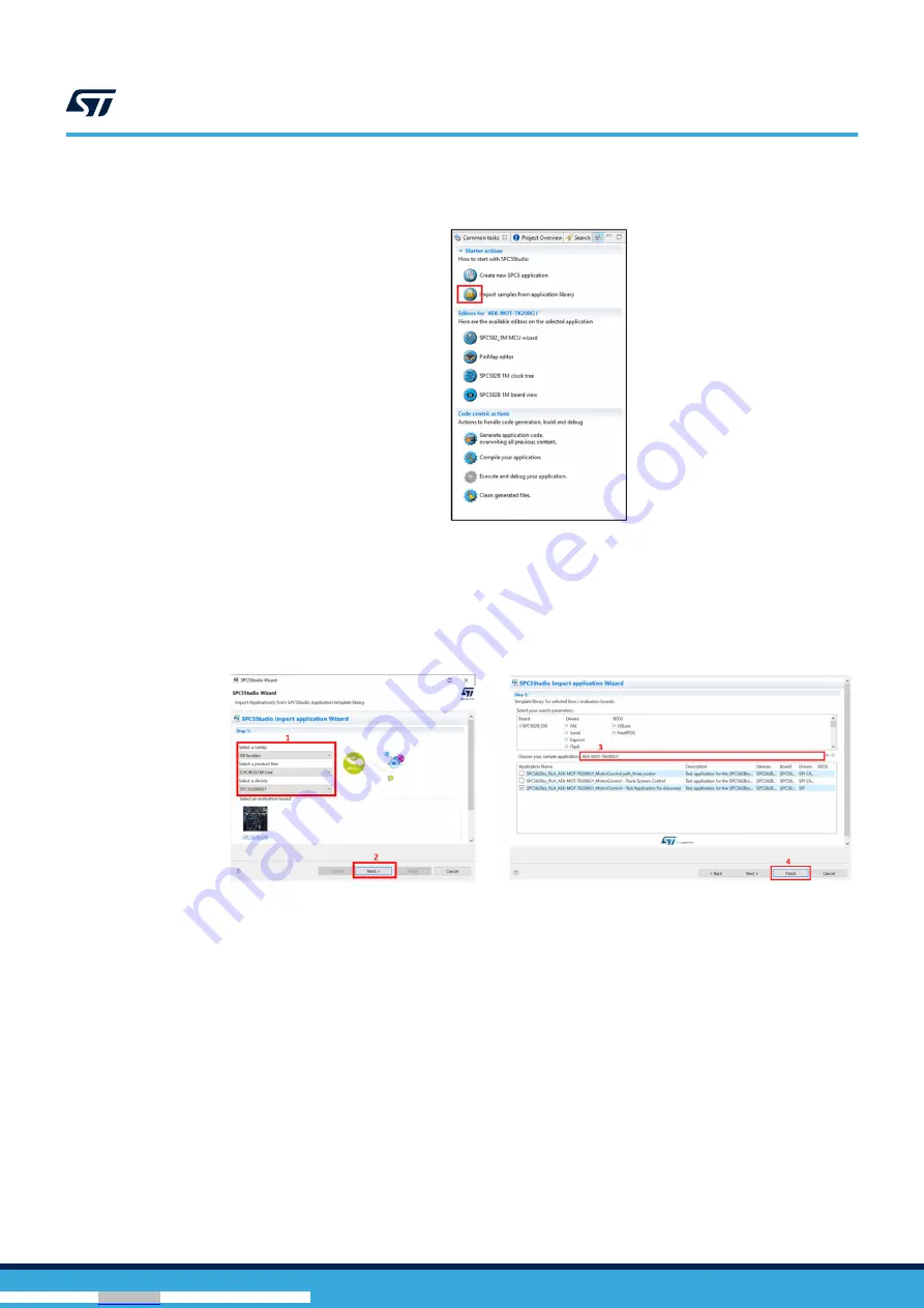
Step 1.

From the [

Common task

] panel, click on the [

Import sample from application library

] icon.

Figure 13. 

Import sample from application library

Step 2.

In the Visual Studio Wizard, from the drop-down menu, select the family, the product, and the device.
Then, click on the next button.

Step 3.

Type “AEK-MOT-TK200G1” in [

Choose your sample application

] text-box.

Step 4.

Tick the demo to import and click on the finish button.

Figure 14. 

MCU and demo selection

3.3

How to locate the AEK-MOT-TK200G1 SW library in the demo

Step 1.

After importing a demo into 

SPC5-STUDIO

, run the code generation.

UM2995

How to locate the AEK-MOT-TK200G1 SW library in the demo

UM2995

 - 

Rev 1

page 13/47

Downloaded from

Arrow.com.

Downloaded from

Arrow.com.

Downloaded from

Arrow.com.

Downloaded from

Arrow.com.

Downloaded from

Arrow.com.

Downloaded from

Arrow.com.

Downloaded from

Arrow.com.

Downloaded from

Arrow.com.

Downloaded from

Arrow.com.

Downloaded from

Arrow.com.

Downloaded from

Arrow.com.

Downloaded from

Arrow.com.

Downloaded from

Arrow.com.

Summary of Contents for AEK-MOT-TK200G1

Page 1: ...a circuitry for the current sensing of the L99DZ200G H bridges outputs has been added On the board this circuit is coupled by two connectors dedicated to Hall sensor feedback coming from the motors T...

Page 2: ...ntual Hall sensors 9 JTAG connector for MCU programming 10 Connector for the two high side outputs 11 Reset button 12 WakeUp_LIN button Figure 2 AEK MOT TK200G1 evaluation board main components 10 8 4...

Page 3: ...ed to raise and lower the tailgate as well as the trunk lock The L99DZ200G can also manage other typical loads located in the power trunk for example buzzer LED and bulb supplies The device standby st...

Page 4: ...TK200G1 H bridges This motor current information can be used for rough position control and obstacle detection during the motor actuation This current sensing network is based on the high side curren...

Page 5: ...force 42 N The computed Rsense soldered on the board is 0 4 Ohms Note Section 6 describes how to change the sensing network according to the chosen motor characteristics 1 1 4 CAN connector and poten...

Page 6: ...keep the device in the active state the MCU activates a watchdog that monitors the communication between the microcontroller and the chip In this state all the outputs are active including the H bridg...

Page 7: ...on must be guaranteed by writing SPI messages into a special register that toggles a specific bit bit 0 of the control register CR1 or Config Reg After the power on or the standby mode the watchdog ha...

Page 8: ...Software architecture APPLICATION AEK_MOT_TK200G1_API LOW LEVEL DRIVERS HARDWARE 2 1 Low level drivers The low level drivers interface with the AEK MOT TK200G1 board They support all the MCU peripher...

Page 9: ...nvert the signal coming from the Hall sensors 2 2 AEK_MOT_TK200G1_API The purpose of the API implemented is to expose all the functions of the AEK MOT TK200G1 board The figure below shows the API func...

Page 10: ...ignificantly simplify the usage of the device by masking the information of the register details The wrapper functions expose at the AEK MOT TK200G1 level features for example motor driving Figure 11...

Page 11: ...writing the L99DZ200G CR1 register that would compromise the watchdog The AEK_MOT_TK200G1_CheckWDExpired function is used for watchdog expiry check and it is included in all the library APIs Moreover...

Page 12: ...ditor to facilitate MCU pin configuration Download the SPC5 UDESTK software to run and debug applications created with SPC5 STUDIO 3 1 2 STSW AUTODEVKIT The STSW AUTODEVKIT plug in for Eclipse extends...

Page 13: ...button Figure 14 MCU and demo selection 3 3 How to locate the AEK MOT TK200G1 SW library in the demo Step 1 After importing a demo into SPC5 STUDIO run the code generation UM2995 How to locate the AE...

Page 14: ...ation is simplified by the Configuration Application tab in SPC5 STUDIO refer to UM2623 paragraph 7 4 The low level drivers to be configured for the AEK MOT TK200G1 board are SPI to implement the bidi...

Page 15: ...are described in the following paragraphs 3 4 1 SPI configuration To configure the SPI according to the AEK MOT TK200G1 hardware requirements follow the procedure below Step 1 Double click on DSPI and...

Page 16: ...ice properly set the parameters in the Transfer section as shown below Figure 20 SPI transfer configuration UM2995 How to configure the low level drivers UM2995 Rev 1 page 16 47 Downloaded from Arrow...

Page 17: ...995 Rev 1 page 17 47 Downloaded from Arrow com Downloaded from Arrow com Downloaded from Arrow com Downloaded from Arrow com Downloaded from Arrow com Downloaded from Arrow com Downloaded from Arrow c...

Page 18: ...PIT configuration 3 4 3 PWM configuration To drive the motors connected to the AEK MOT TK200G1 board with PWM signals configure the eMIOS low level driver Step 1 Double click on eMios Settings in the...

Page 19: ...9DZ200G functionalities are available except the watchdog requirement Thus the watchdog deactivation eases the debug of the microcontroller firmware To enter the debug mode follow the procedure below...

Page 20: ...20 47 Downloaded from Arrow com Downloaded from Arrow com Downloaded from Arrow com Downloaded from Arrow com Downloaded from Arrow com Downloaded from Arrow com Downloaded from Arrow com Downloaded...

Page 21: ...rom Arrow com Downloaded from Arrow com Downloaded from Arrow com Downloaded from Arrow com Downloaded from Arrow com Downloaded from Arrow com Downloaded from Arrow com Downloaded from Arrow com Down...

Page 22: ...oard via CAN Then download the SPC58ECxx_RLA_MainECUFor_AEK MOT TK200G1Control Test Application demo on the board MCU The used APIs are AEK_MOT_TK200G1_Init to initialize the board AEK_MOT_TK200G1_HSO...

Page 23: ...from Arrow com Downloaded from Arrow com Downloaded from Arrow com Downloaded from Arrow com Downloaded from Arrow com Downloaded from Arrow com Downloaded from Arrow com Downloaded from Arrow com Dow...

Page 24: ...temperature or voltage at the VSREG VS or WU pin AEK_MOT_TK200G1_V1Reset Sets the voltage regulator V1 reset threshold VRTH monitored in active or V1_Standby state AEK_MOT_TK200G1_PWMFrequencySetting...

Page 25: ...1 of the H bridges AEK_MOT_TK200G1_SlowDecaySingle Sets the slow decay single for leg 1 of the H bridges AEK_MOT_TK200G1_DSMonitorThreshold Drain source monitoring threshold for the H bridges AEK_MOT...

Page 26: ...in the SPC5 STUDIO In this case it is 5 V This means that the voltage range that the ADC can read is 0 V 5 V Step 4 Calculate the maximum power dissipation of the Rsense In our case Ps 0 025W Step 5...

Page 27: ...the Rsense resistor is the mimimum possible that is Imin 25 mA VRSENSE RSENSE IMIN 0 01V VOUT GAIN VRSENSE VOUT 50 VRSENSE 50 0 01 0 5V Note The layout of the board can accommodate Rsense resistors w...

Page 28: ...om Arrow com Downloaded from Arrow com Downloaded from Arrow com Downloaded from Arrow com Downloaded from Arrow com Downloaded from Arrow com Downloaded from Arrow com Downloaded from Arrow com Downl...

Page 29: ...D Adj U1 LD1117S50TR C2 10uF C9 10uF C10 10nF 1K R7 D5 GND GND C1 47uF C3 220uF BSS138 Q2 WakeUP_mcu VSreg R83 10k STTH3R02AFY UM2995 Rev 1 page 29 47 Downloaded from Arrow com Downloaded from Arrow c...

Page 30: ...A SH1A GL1A GL1A GH2A SH2A GL2A GND PWMH2B PWMH1B PWMH1A PWMH2A PWMH1A PWMH2A PWMH1B PWMH2B PWMH PWMH1A PWMH2A PWMH1B PWMH2B PWMH HB B 1 6 HB A 1 6 TP13 TP14 TP15 TP16 TP17 TP18 TP19 TP20 TP21 TP22 TP...

Page 31: ...ownloaded from Arrow com Downloaded from Arrow com Downloaded from Arrow com Downloaded from Arrow com Downloaded from Arrow com Downloaded from Arrow com Downloaded from Arrow com Downloaded from Arr...

Page 32: ...sition_B 8TP2 9TP2 TP31 TP30 SEL1 Vcc Gain 50 SEL2 Gnd SEL1 Vcc Gain 50 SEL2 Gnd UM2995 Rev 1 page 32 47 Downloaded from Arrow com Downloaded from Arrow com Downloaded from Arrow com Downloaded from A...

Page 33: ...B 46 PM14 CAN4_RX 34 VDD_HV_IO_MAIN 51 50 U6 SPC582B60E1MH00Y PWM1A PWM2A PWM1B PWM2B CLK MISO R701k PI1 ADC35 CAN3_TX DSPI2_CS1 eMIOS Ch4 PA1 CAN2_RX PA2 CAN2_TX R711k MOSI R72 CSN R731k JCOMP TCK TM...

Page 34: ...M 0805C SMD Ceramic Capacitor not mounted 11 13 C30 C41 C42 C47 C48 C55 C56 C61 C64 C66 C69 C72 C75 100nF 0603C 50 V 10 SMD Ceramic Capacitor Wurth Elektronik 885012206095 12 2 C31 C32 22nF 0805C 50 V...

Page 35: ...STTH3R02AFY 26 1 D5 LED Amber 2V WL SMCW_0805 WL SMCW SMT Mono color Chip LED Waterclear size 0805 Amber 2V 140deg_150080AS75000 Wurth Elektronik 150080AS75000 27 2 D6 D7 LED Green 3 2V WL SMCW_0805 W...

Page 36: ...2 Q4 Q5 BSS138 SOT23 N Channel Enhancement Mode Vertical DMOS FET Onsemi BSS138 42 1 Q3 STL64N4F7AG PowerFLAT 5x6 WF STL260N4F7 PowerFLAT 5x6 Automotive grade N channel 40 V 7 0 mOhm typ 64 A STripFET...

Page 37: ...4420V UM2995 Bill of materials UM2995 Rev 1 page 37 47 Downloaded from Arrow com Downloaded from Arrow com Downloaded from Arrow com Downloaded from Arrow com Downloaded from Arrow com Downloaded from...

Page 38: ...PC582B60E1MH00Y 69 1 X1 830059537 WE XTAL_CFPX 104 WE XTAL Quartz Crystal SMT CFPX 104 40MHz 20ppm Wurth Elektronik 830059537 70 1 60900213421 Jumper 2 54mm Wurth Elektronik 60900213421 71 4 970100365...

Page 39: ...ed from Arrow com Downloaded from Arrow com Downloaded from Arrow com Downloaded from Arrow com Downloaded from Arrow com Downloaded from Arrow com Downloaded from Arrow com Downloaded from Arrow com...

Page 40: ...Arrow com Downloaded from Arrow com Downloaded from Arrow com Downloaded from Arrow com Downloaded from Arrow com Downloaded from Arrow com Downloaded from Arrow com Downloaded from Arrow com Downloa...

Page 41: ...ns d valuation uniquement Ce kit g n re utilise et peut mettre de l nergie radiofr quence et n a pas t test pour sa conformit aux limites des appareils informatiques conform ment aux r gles d Industri...

Page 42: ...Arrow com Downloaded from Arrow com Downloaded from Arrow com Downloaded from Arrow com Downloaded from Arrow com Downloaded from Arrow com Downloaded from Arrow com Downloaded from Arrow com Downloa...

Page 43: ...ork 26 7 Motor model used during the AEK MOT TK200G1 emission tests 28 8 Schematic diagrams 29 9 Bill of materials 34 10 Board versions 40 11 Regulatory compliance information 41 UM2995 Contents UM299...

Page 44: ...ded from Arrow com Downloaded from Arrow com Downloaded from Arrow com Downloaded from Arrow com Downloaded from Arrow com Downloaded from Arrow com Downloaded from Arrow com Downloaded from Arrow com...

Page 45: ...d from Arrow com Downloaded from Arrow com Downloaded from Arrow com Downloaded from Arrow com Downloaded from Arrow com Downloaded from Arrow com Downloaded from Arrow com Downloaded from Arrow com D...

Page 46: ...1 circuit schematic 2 of 5 30 Figure 33 AEK MOT TK200G1 circuit schematic 3 of 5 31 Figure 34 AEK MOT TK200G1 circuit schematic 4 of 5 32 Figure 35 AEK MOT TK200G1 circuit schematic 5 of 5 33 UM2995 L...

Page 47: ...y prior versions of this document 2022 STMicroelectronics All rights reserved UM2995 UM2995 Rev 1 page 47 47 Downloaded from Arrow com Downloaded from Arrow com Downloaded from Arrow com Downloaded fr...

Reviews: