4
Deutsch
Anwendung
Schließzylinder-Aufnahme mit zwei-
stufigem Tastkontakt zur Aufnahme
eines bauseitigen Profil-Halbzylinder
nach DIN 18252 mit ca. 40 mm
Gesamtlänge.
Elektrische Spannung
Einbau, Montage und Service-
arbeiten elektrischer Geräte dürfen
ausschließlich durch eine Elektro-
Fachkraft erfolgen.
Montage und Installation
Um den Schließzylinder in die
Schließzylinder-Aufnahme einzu-
setzen, muss die Funktionseinheit
zuerst rückseitig geöffnet werden.
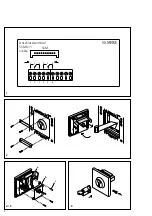
1 Anschlussleiterplatte
mit Prinzipschaltbild (gezeich-
nete Kontaktstellung entspricht
Ruhestellung bei nicht betätigtem
Schlüssel)
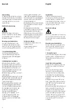
Schließzylinder einsetzen
2
Bedienplatte abnehmen, siehe
Produktinformation zur Türstation.
3
Schließzylinder-Aufnahme an der
Montageplatte losschrauben, von
der Montageplatte abnehmen und
Anschlussstecker abziehen.
4
Abdeckkappe
„a“
lösen und nach
oben klappen.
5
Befestigungsschrauben
„c“
auf der
Rückseite lösen, die Schaltmechanik
„b“
von der Frontplatte abnehmen
und zur Seite legen.
6
Profil-Halbzylinder einsetzen und
mit Befestigungsschraube fixieren.
Auf die Schließbartstellung achten!
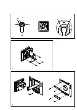
7
Schließbart durch Drehen des
Schlüssels in die gewünschte
Stellung (
I
oder
II
) bringen.
Stellung
„I“
: Schließbart „315°“
in der Schaltgabel geführt. Der
Schlüssel kann nur abgezogen
werden, wenn kein Kontakt betä-
tigt ist.
Stellung
„II“
: Schließbart „45°“
neben der Schaltgabel eingesetzt.
Der Schlüssel kann nur abgezogen
werden, wenn einer der beiden
Kontakte betätigt ist.
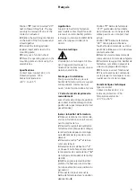
8
Schaltmechanik auf die Rückseite
der Frontplatte aufsetzen und ver-
schrauben.
9
Schließzylinder-Aufnahme
anschließen, einbauen und an der
Montageplatte festschrauben.
10
Funktionsprüfung durchführen
11
Bedienplatte auf die Montage-
platte aufsetzen und mit dem
Montageschlüssel verriegeln.
Technische Daten
Kontaktart: Schließer 24 V, 2 A
Schutzart: IP 54
Umgebungstemperatur:
–20 °C bis +55 °C
Application
Locking cylinder retainer with
two-stage non-holding contact for
accommodating a customer-pro
-
vided profile half cylinder in accord
-
ance with DIN 18252 with a total
length of approx. 40 mm.
Electrical voltage
Mounting, installation and servicing
work on electrical devices may only
be perform
ed by a suitably qua
lified
electrician.
Mounting and installation
To insert the locking cylinder in the
locking cylinder retainer, the func
-
tion unit must first be opened at
the back.
1 Connection pcb
with schematic diagram (The contact
position shown corresponds to the
idle position when the key is not
actuated)
Insert the locking cylinder
2
Take off the operating panel, see
p
roduct information for the door
station.
3
Unscrew the locking cylinder
retainer on the mounting plate,
remove from the mounting plate
and release the connecting plug.
4
Release cover cap
“a”
and hinge
upwards.
5
Release fixing sc
rews
“c”
at the
back, remove the switching mecha-
nism
“b”
from the front panel and
place on one side.
6
Insert the profile half-cylinder and
fa
sten using the fixin
g screw. Pay
attention to the lock bit position.
7
Move the lock bit to the required
position (
I
or
II
) by turning the key.
Position
“I”
: lock bit guided “315°”
into the switching fork. The key can
only be removed if no contact is
actuated.
English


