8
English
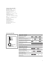
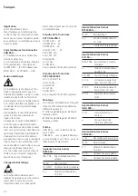
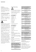
Terminal assignment
BTLM 650-…
Ta, Tb
In-Home bus
b, c
Power supply 12 V AC
Tö
Relay contact door
release
Terminal assignment SG 150-…
TaM , TbM In-Home bus monitor
branch
+, -
Supply voltage
20–50 V DC
ETb, ERT
Storey call button
S1, S1
Potential-free contact
max. 30 V AC/DC, 2 A
E1, E1
galvanically isolated
4–30 V DC, 10 mA
PE, PE
Equipotential bonding
LAN
Terminal assignment ANG 600-…
L1, N
Power connection
+, -
Output voltage
48 V DC, 800 mA
Terminal assignment SNG 850-…
L1, N
Power connection
Ta, Tb
In-Home bus
b, c
Power supply 12 V AC
Tö, Tö
Relay contact door
release
Li, Li
Relay contact light
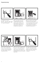
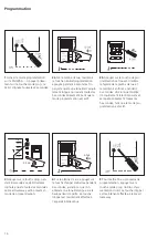
Commissioning
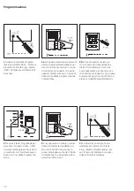
Easy commissioning by means of
manual programming.
Upgrade capability
The set can be extended with further
components. The overall extension
of the set must not exceed 10 users,
whereby one door station supports
two users.
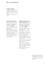
Application
The Smart Gateway Vario/Classic
sets in bus technology contain all the
components you need to accept a
door call with video on your smart
-
phone and open the door.
Performance features SNG 850-…
•
10 bus addresses for supplying the
bus users
• Integrated door release and light
contact
• Programming: manual or via
BPS 650-… (Windows PC) with
ZBVG 650-… and PRI 602-… USB
Electrical voltage
• Mounting, installation and ser-
vicing work on electrical devices may
only be performed by a suitably
qualified electrician. Failure to
observe this regulation could result
in the risk of serious damage to
health or fatal injury due to electric
shocks.
• Operation at an altitude of up to
2000 m above sea level.
•
Observe EN 62368-1! In a building
installation, an all-pole mains switch
with a contact opening of at least
3 mm must be provided. The device
must not be exposed to water drops
or sprayed water! Sufficient ventila
-
tion must be ensured. Pay particular
attention to ensure that ventilation
slots are not covered.
•
When using stranded cores as
cable material, these must be fitted
with wire end ferrules without fail.
Electrostatic charging
As a result of electrostatic charging,
direct contact with the circuit board
can result in destruction of the
device. Direct contact with the circuit
board must therefore be avoided.
Scope of supply SET VVSG 850-1
•
BCM 653-… W
•
BTLM 650-… W
•
BTM 650-… W
•
KR 611-3/1-… W
•
MR 611-3/1-…
•
GU 611-3/1-…
•
ANG 600-…
•
SG 150-…
•
SNG 850-…
• This product information
Scope of supply SET CLVSG 850-1
•
F CL V130 01 B-…
•
GU CL 06-…
•
ANG 600-…
•
SG 150 -…
•
SNG 850-…
• This product information
Mounting
Mounting instructions can be found
in the production information for
the individual devices.
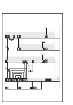
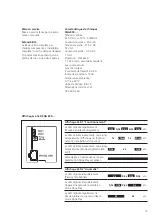
1
Smart Gateway Vario set circuit
diagram
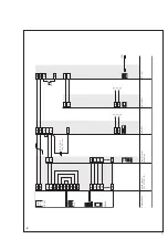
2
Smart Gateway Classic set circuit
diagram
Range
SNG 850-… to door station
max. 100 m,
SNG 850-… to the most remote
indoor device max. 100 m, with
0.8 mm core diameter.
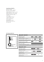
Terminal assignment BCM 653-…
TaK, TbK In-Home bus camera
branch
Ta, Tb
In-Home bus
Vc, GND
Camera actuation
b, c
Power supply 12 V AC


