23
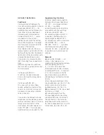
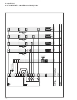
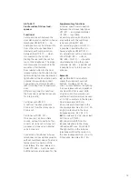
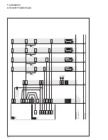
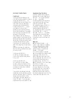
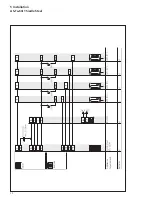
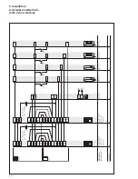
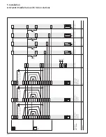
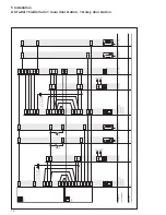
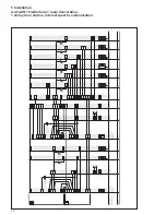
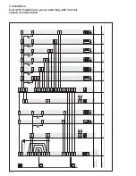
AS-Ta-64/1 Siedle Steel
Functional
Calling and speech between the
door station and connected in-house
telephones HTS/HTC 811-… An
existing call cannot be listened in to
from other in-house telephones.
Internal speech communication
between the HTC 811-…, which
is connected to the GC 612-…
Dialling the user with the call but-
tons on the telephones. The assign-
ment sequence corresponds to the
sequence of call buttons.
Door release button for the door
release function, light button for the
light switching function. Illuminated
light button at the door station with
potential-free switching contact.
Connection of a storey call button
(ERT) for calling from an apartment
door.
Different ring tones for calls from
the front door, apartment door and
for internal calls.
Call tones with HTS 811-…
A call from the door produces a
3-tone call, from the storey door a
2-tone call.
Call tones with HTC 811-…
On a door call, a 3-tone chime
sounds, without connection of ter-
minal G a 3-tone call. A storey call
produces a 2-tone call, an internal
call a 3-tone call.
Connection of additional in-house
telephones or door stations possible
without switchover device. To ensure
tamper-proof connection of the
door release, the door release con-
troller CTÖ 602-… has to be used.
Additional cores are required for this.
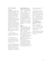
Supplementary functions
• Internal speech communication
between the in-house telephones
HTC 811-… and group controller
GC 612-… is possible.
• Switching and control functions
are possible with the switching/
remote controller SFC 602-…
• A secondary signal unit NS 711-…
is possible in parallel with an in-
house telephone HTS/HTC 811-…
• A parallel door call to a maximum
of 2 HTS/HTC 811-… units or
NSC 602-…/NS 711-… is possible
simultaneously. Using the group
controller GC 612-… a parallel call
is possible to up to 6 in-house tel
-
ephones.
Remarks
a)
Line rectifier NG 602-… can
supply 1 door release and lighting
for appr. 330 call buttons. With
more than 330 illuminated call
button modules, an additional
TR 603-… is required.
• 12 V AC consumers in the AS
plan: Door release appr. 600 mA LED
lighting per call button 3 mA
• Door release contact load in the
door loudspeaker max. 24 V AC, 2 A
• Light contact load in the door
loudspeaker max. 24 V AC, 2 A
b)
Door release 12 V AC, use at least
20 Ohm (e.g. TÖ 615-…)
c)
Conductor length from the
in-house telephone to the storey
call button ERT max. 50 m/164 ft.
The light button in the in-house
telephone switches the contact in
the door loudspeaker from c to Li for
0.8 seconds, load max. 24 V, 2 A.
The Siedle-Steel door station STL …
is fully wired in the factory.
If there are several door stations
integrated in the system, with the
2
nd to the
x
th STL … the door
intercom system must be removed in
each case and the jumpers located
behind it from „+ and 7.1“ to „+
and 7.5“ and also if applicable „+
and 7 …“ must be taken out. For
instructions on how to remove the
jumpers, refer to the Siedle Steel
product information.
In-house telephones which are
connected
to only one
STL -…
must always
be connected to 7.1
to 7.5.
If the in-house telephone is
connected e.g. at terminal 7.4, at
this STL … the jumpers „+ and 7.1“
to „+ and 7.3“, „+ and 7.5“ and
where available also „+ and 7…“
must be taken out.
If there are more than 5 call buttons
at the STL …, these are routed to
the add-on call button extension
circuit board.
Summary of Contents for AS-Ta-64/1
Page 1: ...System Manual 1 n technology Issue 2013 ...
Page 7: ...7 ...
Page 16: ...16 5 Installation AS Ta 64 1 Siedle Vario Remarks Appliance requirement ...
Page 20: ...20 5 Installation AS Ta 64 1 Siedle Classic Remarks Buttons Appliance requirement ...
Page 22: ...22 5 Installation AS Ta 64 1 Siedle Steel Remarks Buttons Appliance requirement ...
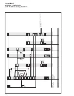
Page 26: ...26 5 Installation AS Ta 64 2 Siedle Vario with 2 door stations Remarks Appliance requirement ...
Page 30: ...30 5 Installation AS Ta 64 3 Siedle Vario with 3 door stations Remarks Appliance requirement ...
Page 53: ...53 ...


