14
Steuerung
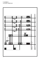
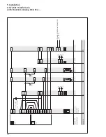
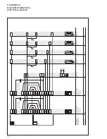
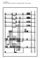
5 Door station installation
Door station installation
The door loudspeaker module
(TLM 612-… and call button module
TM 612-…) are each inserted in the
relevant terminal block. The circuit
diagram illustrates the two terminal
blocks of the TLM 612-… and
TM 612-…
When
switching several doors
in parallel
the terminal TLn must
be connected between the door
stations to allow synchronization
between the door loudspeakers.
The jumper of te between
the door loudspeaker and call button
module must only be inserted at one
door station when switching several
doors in parallel.
Block diagram of door loud-
speaker module TLM 612-…
Terminals of the door loudspeaker
module TLM 612-…
• Potential-free light button T1/T2
• Door release contact c/Dr
• Light contact from telephone c/Li
• Vc actuation for video
• Terminal 6 call voltage
• Terminal 11 call current recognition
• D+/D– actuation for SFC 602-…/
CTÖ 602-…
• 1 reference terminal for 1+n
• TLn for synchronization of several
door stations
• +/– supply voltage 24 V DC
Terminal 1
All in-house telephones
Subdistributor
for NG 602-...
Subdistributor
for NG 602-...
In-house telephone (no.1) terminal 7
In-house telephone (no.2) terminal 7
In-house telephone (no.3) terminal 7
In-house telephone (no.4) terminal 7
Summary of Contents for AS-Ta-64/1
Page 1: ...System Manual 1 n technology Issue 2013 ...
Page 7: ...7 ...
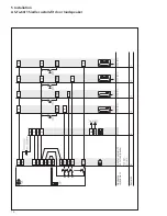
Page 16: ...16 5 Installation AS Ta 64 1 Siedle Vario Remarks Appliance requirement ...
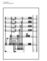
Page 20: ...20 5 Installation AS Ta 64 1 Siedle Classic Remarks Buttons Appliance requirement ...
Page 22: ...22 5 Installation AS Ta 64 1 Siedle Steel Remarks Buttons Appliance requirement ...
Page 26: ...26 5 Installation AS Ta 64 2 Siedle Vario with 2 door stations Remarks Appliance requirement ...
Page 30: ...30 5 Installation AS Ta 64 3 Siedle Vario with 3 door stations Remarks Appliance requirement ...
Page 53: ...53 ...


