


AUTOMATIC TRANSMISSION 5A-19
SSANGYONG Y200
POWER FLOWS
The power flows for the various transmission selections
are listed below;
•
Power Flow - Neutral and Park
•
Power Flow - Reverse
•
Power Flow - Manual 1
•
Power Flow - Drive 1
•
Power Flow - Drive 2
•
Power Flow - Drive 3
•
Power Flow - Drive 3 Lock Up
•
Power Flow - Drive 4 (Overdrive)
•
Power Flow - Drive 4 Lock Up
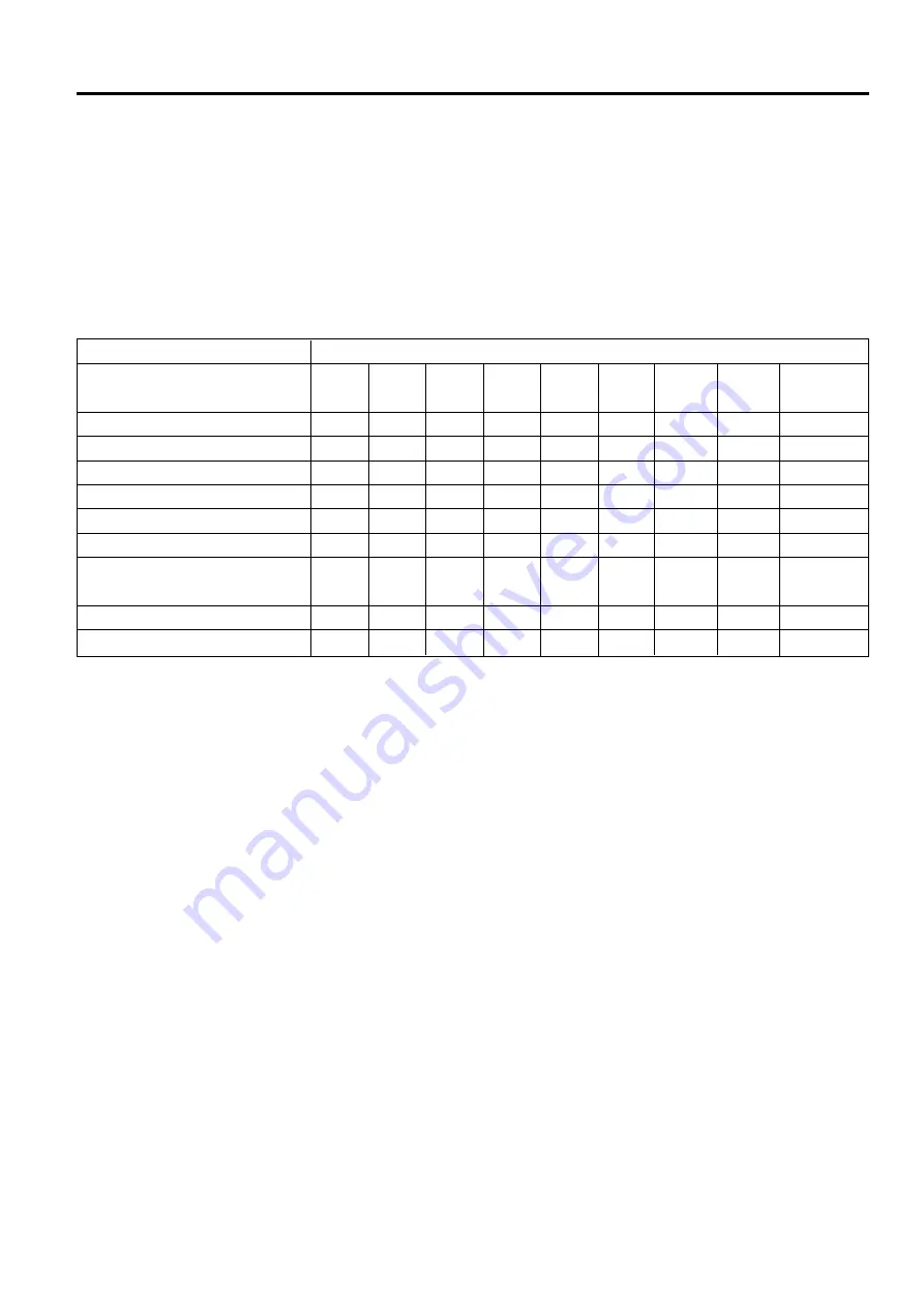
The following table details the engaged elements
versus the gear selected for all transmission selections.
C1
-
-
-
-
-
X
X
X
X
1-2
OWC
-
-
-
X
-
-
-
-
-
3-4
OWC
-
-
X
X
X
X
X
X
X
B2
X
X
X
-
-
-
-
-
-
B1
-
-
-
-
X
-
-
X
X
Gear State
Park and Neutral
Reverse
Manual 1
Drive 1
Drive 2 and Manual 2
Drive 3 and Manual 3
Drive 3 Lock Up and
Manual 3 Lock Up
Drive 4 Overdrive
Drive 4 Lock Up
C2
-
-
X
X
X
X
X
X
X
C3
-
X
-
-
-
-
-
-
-
C4
-
-
X
-
X
X
X
-
-
LU
CLUTCH
-
-
-
-
-
-
X
-
X
ELEMENTS ENGAGED
Summary of Contents for Rexton Y200
Page 21: ...ENGINE GENERAL INFORMATION 1A 7 SSANGYONG Y200 YAD1A050 DIESEL ENGINE Front View ...
Page 22: ...SSANGYONG Y200 1A 8 ENGINE GENERAL INFORMATION Side View YAD1A060 ...
Page 38: ...SSANGYONG Y200 1A 24 ENGINE GENERAL INFORMATION PERFORMANCE CURVE M162 Engine YAD1A160 ...
Page 39: ...ENGINE GENERAL INFORMATION 1A 25 SSANGYONG Y200 M161 Engine YAD1A170 ...
Page 40: ...SSANGYONG Y200 1A 26 ENGINE GENERAL INFORMATION Diesel Engine YAD1A180 ...
Page 63: ...SSANGYONG Y200 1B1 22 M162 ENGINE MECHANICAL ENGINE MOUNT YAD1B300 ...
Page 175: ...SSANGYONG Y200 1B2 14 M161 ENGINE MECHANICAL YAD1B5M0 ENGINE MOUNT ...
Page 272: ...SSANGYONG Y200 1B3 6 DIESEL ENGINE MECHANICAL CYLINDER BLOCK YAD1BA50 ...
Page 274: ...SSANGYONG Y200 1B3 4 DIESEL ENGINE MECHANICAL COMPONENT LOCATOR CYLINDER HEAD YAD1BA40 ...
Page 276: ...SSANGYONG Y200 1B3 8 DIESEL ENGINE MECHANICAL ENGINE COMPONENT YAD1BA60 ...
Page 498: ...M162 ENGINE CONTROLS 1F1 71 SSANGYONG Y200 YAD1F590 ...
Page 592: ...M161 ENGINE CONTROLS 1F2 71 SSANGYONG Y200 YAD1F590 ...
Page 701: ...SSANGYONG Y200 2C 6 FRONT SUSPENSION CROSS SECTIONAL VIEW SUSPENSION ASSEMBLY YAD2C060 ...
Page 704: ...FRONT SUSPENSION 2C 9 SSANGYONG Y200 REPAIR INSTRUCTIONS ON VEHICLE SERVICE YAD2C080 ...
Page 720: ...REAR SUSPENSION 2D 5 SSANGYONG Y200 SHOCK ABSORBER YAD2D040 ...
Page 757: ...SSANGYONG Y200 3A 8 FRONT AXLE YAD3A380 ...
Page 965: ...SSANGYONG Y200 4E 88 ABS AND TCS SCHEMATIC AND ROUTING DIAGRAMS YAD4E280 ABS 5 3 CIRCUIT ...
Page 966: ...ABS AND TCS 4E 89 SSANGYONG Y200 YAD4E290 ABD 5 3 CIRCUIT ...
Page 983: ...AUTOMATIC TRANSMISSION 5A 11 SSANGYONG Y200 HYDRAULIC CONTROL CIRCUIT KAA5A08A ...
Page 992: ...5A 20 AUTOMATIC TRANSMISSION SSANGYONG Y200 PARK AND NEUTRAL KAA5A31A ...
Page 994: ...5A 22 AUTOMATIC TRANSMISSION SSANGYONG Y200 REVERSE KAA5A33A ...
Page 996: ...5A 24 AUTOMATIC TRANSMISSION SSANGYONG Y200 MANUAL 1 KAA5A35A ...
Page 998: ...5A 26 AUTOMATIC TRANSMISSION SSANGYONG Y200 DRIVE 1 KAA5A37A ...
Page 1000: ...5A 28 AUTOMATIC TRANSMISSION SSANGYONG Y200 DRIVE 2 AND MANUAL 2 KAA5A39A ...
Page 1002: ...5A 30 AUTOMATIC TRANSMISSION SSANGYONG Y200 DRIVE 3 AND MANUAL 3 KAA5A41A ...
Page 1004: ...5A 32 AUTOMATIC TRANSMISSION SSANGYONG Y200 DRIVE 3 LOCK UP AND MANUAL 3 LOCK UP KAA5A43A ...
Page 1006: ...5A 34 AUTOMATIC TRANSMISSION SSANGYONG Y200 DRIVE 4 OVERDRIVE KAA5A45A ...
Page 1008: ...5A 36 AUTOMATIC TRANSMISSION SSANGYONG Y200 DRIVE 4 LOCK UP KAA5A47A ...
Page 1071: ...AUTOMATIC TRANSMISSION 5A 203 SSANGYONG Y200 KAA5A2G0 ...
Page 1081: ...AUTOMATIC TRANSMISSION 5A 213 SSANGYONG Y200 TCM WIRING DIAGRAM DIESEL ENGINE 1 OF 2 YAD5A230 ...
Page 1082: ...5A 214 AUTOMATIC TRANSMISSION SSANGYONG Y200 TCM WIRING DIAGRAM DIESEL ENGINE 2 OF 2 YAD5A240 ...
Page 1083: ...AUTOMATIC TRANSMISSION 5A 215 SSANGYONG Y200 CONNECTOR END VIEW KAA5A5O0 ...
Page 1097: ...MANUAL TRANSMISSION 5B 11 SSANGYONG Y200 YAD5B460 TRANSMISSION ASSEMBLY DISASSEMBLED VIEW ...
Page 1167: ...PART TIME T C 5D1 15 SSANGYONG Y200 DIAGNOSTIC DIAGRAM YAD5D210 ...
Page 1170: ...SSANGYONG Y200 5D1 18 PART TIME T C DISASSEMBLY AND ASSEMBLY YAD5D370 ...
Page 1222: ...TRANSFER CASE TOD 5D2 27 SSANGYONG Y200 SCHEMATIC WIRING DIAGRAM YAD5D190 ...
Page 1269: ...SSANGYONG Y200 5D2 74 TRANSFER CASE TOD UNIT REPAIR TRANSFER CASE DISASSEMBLED VIEW YAD5D360 ...
Page 1313: ...SSANGYONG Y200 6E 6 STEERING COLUMN YAD6E050 Side Rear STEERING ASSEMBLY CROSS SECTION ...
Page 1347: ...SSANGYONG Y200 7B 6 GENERAL HVAC SYSTEM Airflow Typical A C System Typical YAD7B020 YAD7B030 ...
Page 1380: ...AUTOMATIC CONTROL HVAC SYSTEM 7D 3 SSANGYONG Y200 FATC CONTROL YAD7D010 ...
Page 1381: ...SSANGYONG Y200 7D 4 AUTOMATIC CONTROL HVAC SYSTEM FATC INPUT OUTPUT ROUTING DIAGRAM YAD7D020 ...
Page 1453: ...BODY INTERIOR 9B 5 SSANGYONG Y200 CONSOLE YAD9B040 ...
Page 1473: ...SSANGYONG Y200 9C 4 BODY EXTERIOR FLIP UP SYSTEM YAD9C030 ...
Page 1540: ...SSANGYONG Y200 9D 12 BODY ELECTRICAL YAD9D190 ...
Page 1541: ...BODY ELECTRICAL 9D 13 SSANGYONG Y200 REPAIR OF EACH SYSTEM INSTRUMENT PANEL ASSEMBLY YAD9D200 ...
Page 1618: ...BODY S MEASURING DIMENSION 9E 3 SSANGYONG Y200 FRAME YAD9E020 ...
Page 1619: ...SSANGYONG Y200 9E 4 BODY S MEASURING DIMENSION YAD9E030 SIDE STRUCTURE COMPLETE ...
Page 1620: ...BODY S MEASURING DIMENSION 9E 5 SSANGYONG Y200 YAD9E040 ...
Page 1621: ...SSANGYONG Y200 9E 6 BODY S MEASURING DIMENSION ENGINE ROOM YAD9E050 ...
Page 1622: ...BODY S MEASURING DIMENSION 9E 7 SSANGYONG Y200 WIND SHIELD AND REAR GLASS YAD9E060 ...
Page 1623: ...SSANGYONG Y200 9E 8 BODY S MEASURING DIMENSION TAIL GATE YAD9E070 ...
Page 1626: ...BODY S MEASURING DIMENSION 9E 11 SSANGYONG Y200 UNDER COATING YAD9E100 ...
Page 1627: ...SSANGYONG Y200 9E 12 BODY S MEASURING DIMENSION YAD9E110 BODY MOUNTING Mounting Point ...


