


1B3-110 OM600 ENGINE MECHANICAL
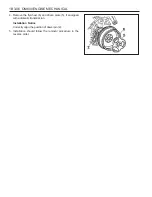
5. Using the press lever (9), press the spring retainer(3)
downward and remove the valve cotters (2) with magnetic
finger (10).
Notice
Be careful not to damage guide bore of the valve tappet.
Press Lever 667 589 00 31 00
Magnetic Finger 116 589 06 63 00
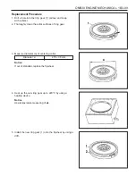
Removal & Installation Procedure
1. Remove the valve tappet (1) with magentic lifter.
Notice
Place the valve tappets upside down (open end upward)
Magentic Liter 102 589 03 40 00
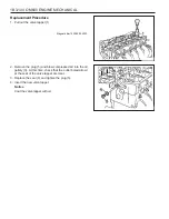
2. Install the holding wheel (7) into the timing chain of camshaft
sprocket piston.
Holding Wheel 603 589 01 40 00
3. Position the piston of relevant cylinder at TDC.
4. Install the supporting bar (8).
Supporting Bar 667 589 02 63 00
Summary of Contents for OM600
Page 12: ...1B3 12 OM600 ENGINE MECHANICAL MAINTENANCE AND REPAIR ON VEHICLE SERVICE ENGINE ASSEMBLY ...
Page 51: ...OM600 ENGINE MECHANICAL 1B3 51 49 Remove the cylinder head 2 and gasket 3 OM661LA ...
Page 145: ...OM600 ENGINE MECHANICAL 1B3 145 CHAIN TENSIONER 1 Chain Tensioner 80Nm 2 Seal Replace ...
Page 171: ...1B3 172 OM600ENGINE MECHANICAL Oil Circulation ...
Page 172: ...OM600 ENGINE MECHANICAL 1B3 173 Oil Filter a From Oil Pump b To Main Oil Gallery c To Oil Pan ...