22
2 Operation
Source
Shaft
Inner (N=5)
Outer (N=6)
Edge
CONFIGURATION
×1
Multiplier
Control
T
Source
= T
Shaft
T
Source
Phase = -90°
φ
Shaft
- φ
Blade
Shaft
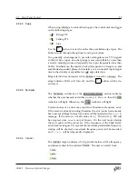
Figure 2.4:
Simulated timing diagram of rear‑panel outputs for
Shaft
control
with ‑90
°
phase offset. Width of
Rotor Shaft Ref Out
pulse is exaggerated for
illustrative purposes.
in every fifth rising edge of
Source Output
to be aligned to the rising
edges of
Rotor Shaft Ref Out
. The same systematic offset
𝜙
shaft
− 𝜙
blade
described above will still be present.
Source
Shaft
Inner (N=5)
Outer (N=6)
Edge
CONFIGURATION
×1
Multiplier
Control
T
Source
T
Inner
= T
Source
φ
Shaft
- φ
Blade
Inner
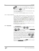
Figure 2.5:
Simulated timing diagram of rear‑panel outputs for Inner Slots con‑
trol with
𝑛
slots
= 5
and 0
°
phase offset. Width of
Rotor Shaft Ref Out
pulse is
exaggerated for illustrative purposes.
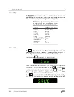
By properly adjusting the
Phase
setting of the Inner track, the user can
correct for this systematic phase offset. Figure 2.6 shows that by adjust‑
ing the phase setpoint to +90
°
, the
Inner Slots Ref Out
can be be brought
into phase alignment with
Source Out
. This amounts to a mechanical
phase advanced of +18
°
mech.
SR542 Precision Optical Chopper


