background image

Model SR465 Platform Installation Procedure

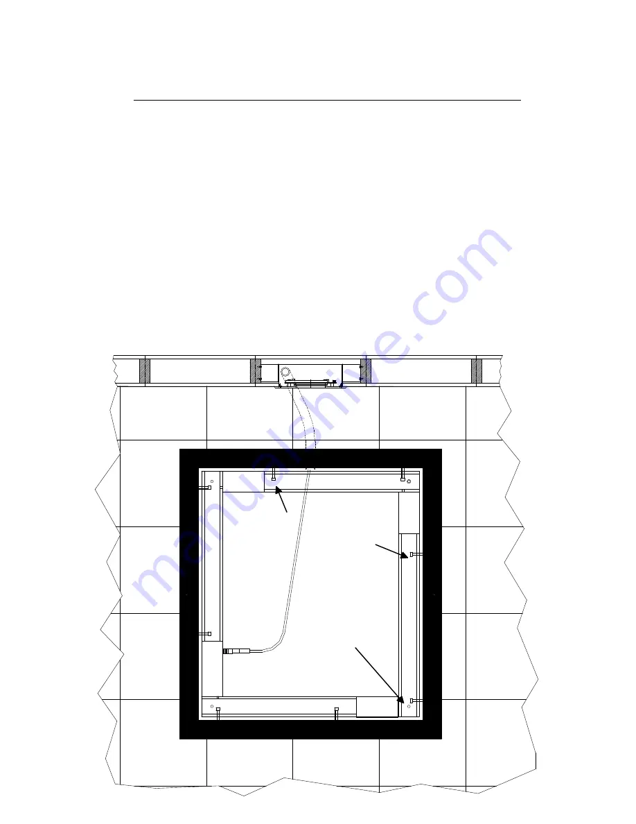
NOTE: PIT FRAME OUTSIDE DIMENSIONS-    3" HIGH    38" WIDE    42" LONG

1.


Carefully unpackage the scale platform and inspect to ensure there has been no shipping damage.

2.

 Prepare the pit area to accept the scale platform and readout as described in fig. 1, below. 

3.

 Mount the readout on the wall and run the connector cable down the conduit to the pit as described in fig. 1 below.

4.

 Remove the platform deck by using the 1/4" hex wrench (supplied) to remove the 

4

 mounting screws on the cover.

5.

 Place the platform into the pit so that the connector for the readout cable is nearest to the conduit.

6.

 Plug the readout cable into the connector on the platform.

7.

 Position the platform in the pit so that the frame is equally spaced from all sides of the pit.

8.

 Using a 9/16" socket wrench, adjust the 

4 corner leveler bolts


(A)

 so that the platform base is one inch (1") below the

surface of the floor on all sides. This will ensure that the deck is even with the floor surface when installed. NOTE: If you
are planning on tiling or carpeting the deck be sure to compensate for the thickness of material. You may place the deck
on the platform to check the level as you make your adjustments.

9.

 When the 

4 corners

 are done, adjust the  remaining level bolts so that they make contact with the floor of the pit then

back them off a 

1/4 turn.

10.

 When your level adjustments are complete tighten the locking nuts on 

all 6

 level bolts to lock them in place.

11.

 Adjust the

 6

 side clearance adjustment bolts 

(B)

 so that the platform is spaced equally on all sides of the pit then tighten

the locking nuts on 

all six (6)bolts

.

12.

 Set the deck on to the platform and secure in place with the 

4

 top mounting screws.

If

you

ha

ve

any

qu

esti
ons

ple

ase

call

the

fac

tor

y

at

1(8

00)

65

4-6

36

0

Part No. MAN465

                                                                                                                                                           rev: 000706

8 SIDE CLEARANCE

ADJUSTMENT BOLTS

4 CORNER
LEVEL BOLTS

Summary of Contents for SRScales SR465

Page 1: ...S S by SR Instruments Inc Model SR465 In Floor Platform Scale System OWNERS MANUAL SR Instruments Inc 600 Young Street Tonawanda NY 14150 Tel 888 WEIGH ME Fax 716 693 5854 Part No MAN465 rev 000706 ...

Page 2: ...ions Page 1 System Operation and button Functions Page 2 SECTION II TECHNICAL SERVICE INFORMATION Calibration and Maintenance Page 4 Care and Cleaning Page 5 Schematic Diagram Page 6 Part List and Component Layout Page 7 Platform Installation Instructions Page 8 Part No MAN465 rev 000706 ...

Page 3: ...from six 6 common D cell alkaline batteries which will provide over 20 000 weight reading before needing replacement This eliminates the need for an external battery charger or an A C outlet The Patient s weight is displayed on a user friendly 16 character dot matrix liquid crystal display This display uses bright green L E D back lighting for superior visibility in all lighting conditions With th...

Page 4: ...with the weighing surface so that the system zero will be accurate In a few moments the display will read WEIGHT 0 0 Lb The display mode will automatically default to the last mode used If after positioning the patient on to the scale system the display shuts off before you are able to view the weight data simply press the WEIGH button to WAKE the display and view the patient s weight NOTE It is r...

Page 5: ...SECTION II TECHNICAL SERVICE INFORMATION For Sales Product Information and Technical Assistance Please Call 1 800 654 6360 Part No MAN465 rev 000706 ...

Page 6: ... in the CAL MODE press the ZERO button to zero the display 4 Place a known calibrated weight on to the weighing surface and compare it to the displayed reading 5 Use the LEFT CAL button to make corrections and the RIGHT button to make corrections to the displayed weight The displayed value should be within 0 1 of the calibrated weight plus or minus 1 digit of reading When adjustments are completed...

Page 7: ...mend mild soap and water for general cleaning The floor transducer is covered by a Stainless Steel plate and may be vacuumed or swept BATTERY REPLACEMENT model SR465 only When battery replacement is necessary the display will indicate REPLACE BATTERY To replace the batteries 1 Remove the instruction cover plate to expose the battery compartment 2 Replace ALL SIX 6 Batteries as shown 3 Replace the ...

Page 8: ...SCHEMATIC and COMPONENT LAYOUT Part No MAN465 rev 000706 ...

Page 9: ...SISTOR VOLTAGE REF ZVNL110 1 Q1 SE1857D255 ET2N3906 TRANSISTOR 2N3906 MATOROLA 1 Q2 SE1857D255 ER17505W3 75 OHM 3 WATT 5 RESISTOR 1 R2 SE1857D255 EV5KKVSF82 5 K POTENTIOMETER 1 R1 SE1857D255 ER41005QF 10K 1 4 WATT 5 RESISTOR 2 R3 R4 SE1857D255 ER62001EF 2MEG 1 RES 1 R5 SE1857D255 ER57503EJ 750K 1 8 WATT 1 J RESISTOR 1 R12 SE1857D255 ER44531EJ 45 3K 1 8 WATT 1 J RESISTOR 2 R6 R8 SE1857D255 ER43241E...

Page 10: ...er bolts A so that the platform base is one inch 1 below the surface of the floor on all sides This will ensure that the deck is even with the floor surface when installed NOTE If you are planning on tiling or carpeting the deck be sure to compensate for the thickness of material You may place the deck on the platform to check the level as you make your adjustments 9 When the 4 corners are done ad...

Page 11: ...Part No MAN465 rev 000706 ...

Page 12: ...Part No MAN465 rev 000706 ...

Reviews: