background image

20

Place the locator over the estimated position of the sonde: 
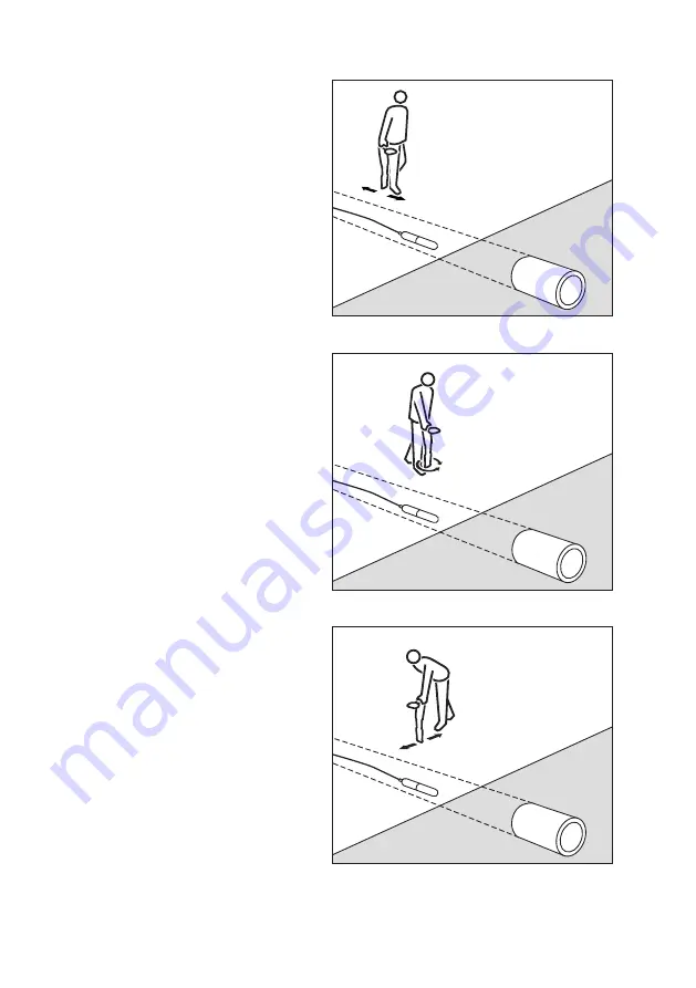
1.  Refer to Figure 1. 

Move the locator backwards and 

forwards with the blade in-line with 

the sonde. Stop when the locator 

display indicates a clear peak 

response.

2.  Refer to Figure 2. 

Rotate the locator as if the blade 

were a pivot, stop when the display 

indicates a clear peak response.

3.  Refer to Figure 3. 

Move the locator from side to side 

until the display indicates a clear peak 

response.

4.  Repeat Steps 1 to 3 in smaller 

increments with the locator blade 

resting on or near the ground. The 

locator should now be directly above 

the sonde with the blade in line with 

the sonde. Now mark the position.

5.  Propel the sonde a further three to 

four paces along the drain or duct 

and pinpoint and mark. Repeat this 

procedure along the route at similar 

intervals. It should only be necessary 

to change the locator sensitivity while 

tracing the sonde if there is a change 

in the depth of the drain or duct, or 

the distance between locator and 

sonde.

Figure1

Figure2

Figure3

Summary of Contents for CUES ACCUPOINT MS611

Page 1: ...Sewer and storm industry sonde and line locator kits User Guide...

Page 2: ...2...

Page 3: ...e attempting to operate the ACCUPOINT locator and transmitter This guide is intended as a quick reference guide only For detailed instructions including the use of accessories help with eCert please r...

Page 4: ...hether a signal is from a single cable or from several in close proximity WARNING Batteries can get hot after prolonged use at full output power Take care while replacing or handling batteries WARNING...

Page 5: ...is safety equipment which should be regularly checked to ensure its correct operation eCert provides a thorough test of the ACCUPOINT s locating circuitry and supplies a CUES Calibration Certificate...

Page 6: ...6 9 ACCUPOINT MS611 locator 6 7 11 12 13 14 13 15 16 17 17 26 28 18 19 20 21 22 24 27 25 23 10 1 2 4 5 3 8...

Page 7: ...en icons 15 Signal strength bargraph with peak marker 16 Signal strength readout 17 Proportional Guidance arrows 18 Battery level 19 Sensitivity readout 20 Volume level 21 Power Mode icon 22 Accessory...

Page 8: ...8 MS620 transmitter 4 2 1 3 10 11 12 13 14 15 16 17 18 5 6 7 8 9...

Page 9: ...e key Transmitter screen icons 10 Battery level indicator 11 Operation mode readout 12 Standby icon 13 Output level indicator 14 Clamp icon Indicates when a signal clamp or other accessory is connecte...

Page 10: ...signals and Increase and decrease gain Accupoint automatically sets gain to mid point when pressed Rapidly increase and decrease gain steps in 1dB increments KEY SHORT PRESS LONG PRESS Enter the menu...

Page 11: ...ter from a mains or vehicle power source using a CUES supplied optional accessory adapter System setup It is important that you set up the system according to regional operational requirements and you...

Page 12: ...OW Select proportional Guidance arrows in Peak mode COMPA Enable or disable display of the Compass feature VALRT Enable or disable the vibration feature AUDIO Select High or Low sound levels SWING Ena...

Page 13: ...u using the or arrows 3 Press the key on the locator or the key on the transmitter to enter the BATT menu 4 Scroll up or down to select the correct battery type Alkaline or Nickel metal Hydride 5 Pres...

Page 14: ...to the pipe or cable you wish to survey using the red Direct Connect lead supplied The black lead is generally connected to earth using the supplied ground stake The transmitter will then apply a dis...

Page 15: ...tworks Once in Power Mode press the key to switch out of CUES s sensitive Power Mode and scroll through five individual Power Filters This enables operators to establish if a single large power signal...

Page 16: ...ld be moved towards the target line The target position indicator indicates the target positioned to the right of the locator and can be used to guide the locator towards the target line The signal st...

Page 17: ...et line enabling both depth and current readings to be displayed As the locator is moved towards the left the tail on the proportional right arrow will reduce the target position indicator will move f...

Page 18: ...urements Using accessories Sondes Flexrods and FlexiTrace Sondes are transmitters that are useful for tracing non metallic pipes and sewer and storm pipelines Battery powered sondes can be fixed to Fl...

Page 19: ...r set to maximum With the sonde in place at the survey location hold the locator vertically and directly over the sonde s estimated position Make sure the blade is in line with the sonde Adjust the se...

Page 20: ...display indicates a clear peak response 4 Repeat Steps 1 to 3 in smaller increments with the locator blade resting on or near the ground The locator should now be directly above the sonde with the bla...

Page 21: ...lty Batteries and power supply Only use the rechargeable battery packs chargers and power supplies approved by CUES If not using rechargeable packs use good quality Alkaline or NiMH batteries only Bat...

Page 22: ...cturer s warranty and may damage the equipment or reduce its performance Service and maintenance Regularly check your equipment for correct operation by using the Self Test function and eCert The loca...

Page 23: ...m PC companion and it allows you to manage and customize your locator ACCUPOINT Manager Online is also used to retrieve and analyze survey and usage data run an eCert calibration and to perform softwa...

Page 24: ...ole or in part without the prior written consent of CUES Inc Due to a policy of continued development we reserve the right to alter or amend any published specification without notice Trademarks CUES...

Reviews: