


14
Operation
19.
IR COMP:
Speed droop on heavy loads may occur where armature voltage feedback is
used. Compensate for this by clockwise adjustment of the
IR comp
preset. Excessive
rotation may lead to instability.
The drive is now commisioned to use Armature Voltage feedback.
17.
MIN SPEED
: The Min spd potentiometer can now adjust between 0% and 30%. (This
assumes that a 10K potentiometer is being used to provide the speed setpoint at
terminals 1, 2 and 3.)
18.
UP & DOWN RAMPS
:
Set the ramp up rate as required (from 20 seconds to 1 second).
Note that the DOWN RAMP rate becomes the UP RAMP rate for negative inputs to
Terminal 3.
16.
Speed Feedback selection:
Set the correct
Armature Voltage
using the
Spd x 2
switch
and the
Max spd
preset:
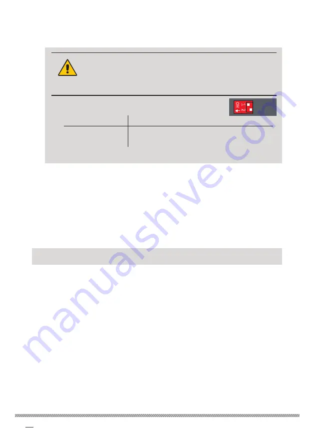
WARNING!
PERSONAL INJURY AND/OR
EQUIPMENT DAMAGE HAZARD
If you change the Spd x 2 switch position while running, the speed will
undergo an immediate step change.
a. Set the
Spd x 2
switch to suit the drive's armature voltage
rating (ranges given below):
340i / 680i / 1220i
340i LV60 / 680i LV60 / 1220i LV60
OFF
40 to 100 V
OFF
10 to 25 V
ON
0 to 200 V
ON
23 to 50 V
b. Adjust the
Max spd
potentiometer setting to achieve the required shaft speed.
Max spd
Min spd
Ramp
Ramp
Stab
O
N
1
2
Stall
Avf/Tach
Spd x 2
Alarm
Level: relay driver threshold. +/-(0.5% to 105%). (+/-10.5V).
Symmetrical about zero.
Increasing brightness indicates imminent trip.
Ramp up: rotate clockwise for a faster response. 20 to 1 seconds up ramp
rate. For +100% speed change.
Minimum speed: rotate clockwise to increase minimum speed.
* 5K potentiometer provides 0 to 30% of maximum speed.
“Fan failure” alarm is active when lit.
Refer to text.
Maximum speed: rotate clockwise to increase speed, 40 V to 200 V
(armature or tach feedback Volts).
LV60 model has Avf range 10 V to 50 V.
O
N
1
2
Avf/Tach
Spd x 2
ANTI-CLOCKWISE
MID-WAY
CLOCKWISE
*
Assumes using a 10K
speed reference
potentiometer
I max
IR comp
Power
Power is present when lit. The LED is brighter for positive current.
IR compensation: rotate clockwise to increase level of armature voltage
droop compensation. 0 to 25%. Excessive rotation may cause instability.
Always set fully anti-clockwise in Tacho mode.
Level
Ramp down: rotate clockwise for a faster response. 20 to 1 seconds
down ramp rate. For -100% speed change.
Maximum current: rotate clockwise to increase current limit.
0 to 100% current limit.
Stability: gain 1 to 10.
DANGER!
ELECTRIC
SHOCK
HAZARD
MOTOR
ARMATURE
MOTOR
FIELD
AC
SUPPLY
A+
A-
F-
F+
N
L
2-pole
AC supply
switch or
contactor
semi-
conductor
fuse
For armatures
with a time constant of
less than 5 ms,a DC choke
must be wired in series
SUPPLY SELECT
110
240
10K
1
+10
2
MIN
3
IP
4
COM
5
IP+/-
6
PB+
7
8
9
10
12
13
14
15
16
17
18
19
20
21
Acw
Cw
START or
RAMP TO STOP
switch
OP+/-
PB-
RUN
COM
11
Tach
RLOP
RLIP
OVLD
ROP
DEM
SOP
RUN switch
Close to COMMON
Open for coast to STOP
TRIP
IOP
SPD
TRQ
Optional TACH
for
speed feedback
Optional
current indicator
+7.5 V = 150%
Optional
speed indicator
+5 V = 100%
DANGER!
ELECTRIC
SHOCK
HAZARD
Earth
Wiring for ON OFF switch with ramp or coast to stop
10K
1
+10
2
MIN
3
IP
4
COM
5
IP+/-
6
PB+
7
8
9
10
Acw
Cw
START or
RAMP TO STOP
switch
OP+/-
PB-
RUN
COM
11
Tach
RUN switch
Close to COMMON
Open for coast to STOP
Optional TACH
for
speed feedback
DANGER!
ELECTRIC
SHOCK
HAZARD
Earth
Basic single direction speed control with tach feedback
USER ADJUSTMENTS
COM
5
PB+
7
8
PB-
IP+/-
6
+/-0 to 10.5 V
4
OP+/-
closed
closed
closed
open
open
closed
open
open
Terminal 7
Terminal 8
*
INVERT
NON-INVERT
INVERT
Mode
No effect on selected mode
Powers-up in INVERT
*
+/-0 to 10.5 V


