Spring Air Systems AP10C Maintenance Manual Download Page 23

_____________________________________________________________________________________________ 

Spring Air Systems Water Wash Ventilator Maintenance Manual 11/01 

21 

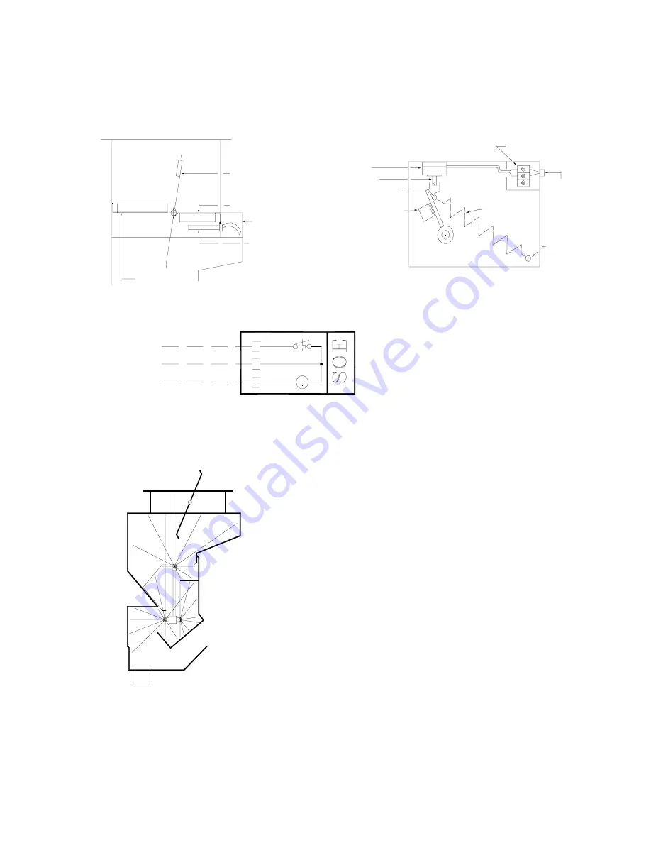
Arrangement “T”: Thermostat Activated 

The arrangement “T” hood and damper assembly consists of a thermostatically activated spring loaded fire damper 
electrically connected to the water wash control panel by three wires. 


Arrangement “T” Fire Damper 

Figure 21 


In addition the surface fire suppression system connect to terminals 5 & 1 the 
Arrangement “T” fire damper SOE enclosure is connected to terminals 1, 2, & 4. 
 
In the event of a fire in the grease extractor the thermostat mounted in the duct 
collar is set to activate at 350 F.  The thermostat energizes a solenoid, which 
pulls a pin within the Fire Damper Solenoid Enclosure (SOE) releasing the fire 
damper.  The spring-loaded fire damper closes tight against a 40 lb. spring 
force.  The thermostat also activates the wash control panel through terminal 2. 

Within the water wash control panel the fire relay R5 is energized activating the 
water wash control panel hood and damper assembly. 

1. 

The exhaust fan is shut off. 

2. 

The hot water solenoid valve is energized releasing water into the interior 
of the grease extractor.  

 
After the fire has been extinguished, rotating a lever on the outside of the FIRE 
DAMPER JUNCTION BOX - SOE, manually resets the fire damper. 


Arrangement “T” & “F” Activated 
 

     Figure 22 


ELECTRICAL WIRING TO SOE ENCLOSURE

SECTION VIEW DAMPER OPEN

DAMPER SOLENOID

4

FENWALL DETECTOR

1

2

DAMPER BLADE

STOPS

DAMPER BLADE STOPS

DAMPER BLADE STOPS

THERMOSTAT

THERMOSTAT J-BOX

DAMPER BLADE

120V/1/60 - 3 AMPS - WIRE EACH SOE IN PARALLEL.

THREE (3) WIRES TO EACH SOE ENCLOSURE LOCATED
AT EACH EXHAUST DUCT COLLAR ON EVERY HOOD

SIDE VIEW DAMPER OPEN POSITION

SOE ENCLOSURE

ARRANGEMENT "T" FIRE DAMPER:

DAMPER RETAINING

(DAMPER OPEN POSITION)

POSITION.

PIN BACK BACK STOP

CLIP

FIRE DAMPER PIN

SOLENOID

SOLENOID PIN

DAMPER RETAINING

CLIP - DOWN

ON TOP OF
VENTILATOR

SPRING
RETAINING
POST

DAMPER CLOSURE
SPRING

BX CONDUIT
TO J-BOX

TERMINAL BLOCKS

Summary of Contents for AP10C

Page 1: ...VENTILATOR MAINTENANCE MANUAL ___________________________ Spring Air Systems Inc Oakville Ontario Phone 905 338 2999 Fax 905 338 0179...

Page 2: ...d Line Fire Suppression Arrangement T 21 Second Line Fire Suppression Arrangement F 22 Variflow Baffles 23 SB10H One Sequence Wash Plumbing Schematic 24 SBA10C One Sequence Wash Plumbing Schematic 25...

Page 3: ...l with all the edges ground and polished All ventilators are manufactured to stringent quality standards and are guaranteed to enhance the appearance of any commercial kitchen Model HT B Water wash Ve...

Page 4: ...water wash D Dry Grease Extractor T Thermostatic Fire Damper F Fusible link spring loaded fire damper D Fusible link dead weight fire damper S Shelf type hood B Box type hood BS Box shelf type hood D...

Page 5: ...rgized through terminals 4 9 When a motorized damper with end switch is not used in the installation the field electrician must jumper terminals 8 9 in the water wash panel to provide 120V 1 60 power...

Page 6: ...continues for the period of time set on the wash timer adjustable from 0 to 600 seconds At the end of the wash cycle the blue WASH pilot the detergent pump and the hot water solenoid valve shut off Th...

Page 7: ...2 4 Hot water solenoid valve 2 H3 4 Hot water solenoid valve 3 OPTIONAL COLD WATER SOLENOID HOT WATER SOLENOID H C FAN PILOT WASH PILOT B PUMP DETERGENT G SMART RELAY Q 1 2 3 4 RUN INTERNAL WIRING BY...

Page 8: ...systems MP40C MP40H Water Wash Panel Figure 9 H2 H3 WASH PILOT 3 WASH PILOT 2 HOT WATER SOLENOID 3 HOT WATER SOLENOID 2 B B I1 Q 1 2 3 4 RUN SMART RELAY INTERNAL WIRING BY SPRING AIR I1 SMART RELAY Q...

Page 9: ...Breaker Figure 10 CLEANING THE EXTERIOR Normal soil can be removed with a mild detergent water mixture applied to a cloth To remove baked on grease apply a cleanser to a damp cloth or sponge and rub...

Page 10: ...WASH SYSTEMS SBA10H SBA10C AP10H AP10C AP20H AP20C AP30H AP30C AP40H AP40C AP50H AP50C The automatic wash control panels are equipped with a solid state microprocessor The fan selector switch is repla...

Page 11: ...ng until the correct hour appears 4 To change the time press once The hour will be highlighted Press 1 Press these two buttons together Su 11 25 Q 1 2 3 4 I 1 2 3 4 5 6 Su 11 25 Set Clock 11 11 01 MM...

Page 12: ...bove settings press 4 The clock has been factory set to turn the fan on at 6 00 a m and off to the minute the fan stop in the evening Press to change the minutes to change the hour you want the fan to...

Page 13: ...the hour that the fan will stop in the evening Press to change the hour you want the fan to stop each evening Press to move to the minute the fan stop in the evening Press to change the minutes to the...

Page 14: ...minutes 4 The clock has been factory set to turn the fan on at 6 00 a m and off at 23 00 hours or 11 00 p m When the fan shuts off the wash activates To change these times see section Programming the...

Page 15: ...120V 1 60 2 AMPS MAXIMUM OPTIONAL POWER SUPPLY TO SUPPLY FAN LV10 PANEL 120V 1 60 2 AMPS MAXIMUM POWER TO THE SPRING AIR SYSTEMS ENVIRO FILTER UNIT POWER TO THE EXHAUST FAN MOTOR STARTER DAMPER END SW...

Page 16: ...secondary coverage as the exhaust air enters the secondary grease extraction chamber The exhaust air continues into the secondary extraction chamber which contains an additional baffle F Residual gre...

Page 17: ...TYPE RECOMMENDED COOKING USE Type C Medium heavy and heavy duty Mesquites live charcoal Gas charbroilers heavy frying Type H Medium and medium heavy duty Gas charbroilers Fryers Ranges Griddles Most c...

Page 18: ...ater wash time because of the continuous cold water spray During fan and cooking operation the spray continuously carries grease dirt and lint down the drain which reduces the daily grease build up Th...

Page 19: ...nstallation Remote wiring and plumbing are shown for an exhaust fan wet chemical systems a Spring Air Systems water wash hood and a SB10H water wash panel In addition to the wiring indicated below pow...

Page 20: ...1 0 3353 7 3 8 9 40 5 50 0 11 5 3505 7 9 9 7 44 2 54 0 12 0 3658 7 9 9 7 44 2 54 0 12 5 3810 8 5 10 4 47 4 57 9 13 0 3962 8 5 10 4 47 4 57 9 13 5 4115 9 2 11 3 51 4 63 0 14 0 4207 9 2 11 3 51 4 63 0 1...

Page 21: ...7 1 14 5 4420 17 6 21 5 66 6 81 3 15 0 4772 17 6 21 5 66 6 81 3 Chart No 3 Cold Water Required Model DB Ventilator Length Cold Water Flow USGPM Cold Water Flow l s Ventilator Length Cold Water Flow US...

Page 22: ...fan motor starter is shut off NOTE The exhaust fan remains on after a primary surface fire suppression system has activated Arrangement D Fusible Link Activated Dead Weight The arrangement D hood and...

Page 23: ...e wash control panel through terminal 2 Within the water wash control panel the fire relay R5 is energized activating the water wash control panel hood and damper assembly 1 The exhaust fan is shut of...

Page 24: ...STITUTE FOR THE SURFACE FIRE SUPPRESSION SYSTEM WET CHEMICAL SPRINKLER ETC A SURFACE FIRE PROTECTION MUST BE INSTALLED IN ACCORDANCE WITH APPLICABLE CODES Arrangement F Fusible Link Activated Spring L...

Page 25: ...ARIFLOW baffles located above a charbroiler are opened to the maximum 450 CFM ft position and the VARIFLOW baffles located above ovens or steamers are closed to the minimum 90 CFM ft position This var...

Page 26: ...n at about 300 CFM ft The baffles are connected to the Primary baffle on studs fastened by wing nuts There a total of five 5 adjustment positions on each baffle After the water wash hood is installed...

Page 27: ..._____________________ Spring Air Systems Water Wash Ventilator Maintenance Manual 11 01 25 SBA10C hot water wash cold water spray plumbing Figure 29 MP20C two sequence hot water wash cold water spray...

Page 28: ..._________________________________________________________ Spring Air Systems Water Wash Ventilator Maintenance Manual 11 01 26 AP30C three sequence hot water wash plumbing Figure 32 MP30H three sequen...

Page 29: ...T WASH PILOT B PUMP WATER SOLENOID OPTIONAL COLD FAN PILOT G 1 5 INTERNAL WIRING BY SPRING AIR FIRE TEST PUMP TEST I3 FAN SWITCH Q 1 2 3 4 RUN Mo 09 00 I 1 2 3 4 5 6 SMART RELAY Q1 Q2 N L I1 I2 OFF AU...

Page 30: ...WO 2 WIRES TO EACH ENS ENCLOSURE LOCATED FENWALL DETECTOR DAMPER SOLENOID END SWITCH NORMALLY OPEN OR x x o x o x o o x H2 H3 WASH PILOT 3 WASH PILOT 2 HOT WATER SOLENOID 3 HOT WATER SOLENOID 2 B B I1...

Page 31: ...check the VORTEX BAFFLE and grease trough for any debris Check that the drain is free and clear SIX MONTHS 1 Clean all line strainers located in the control panel hot water and cold water 2 Check exha...

Page 32: ...he throat inlet slot of the ventilator Velometer should not exceed three inches in diameter Measuring Exhaust Air Figure 38 PITOT TUBE OR ANEMOMETER Hold the instrument perpendicular to the VORTEX BAF...

Page 33: ...er drawings 6 Check that all electrical connections are tight and secure 7 Check exhaust duct connections 8 Check that fire damper is open 9 Open ventilator access door and check drain and grease trou...

Page 34: ...amper only iii Faulty end switch in Fire Damper End Switch Enclosure ENS Arrangement F dampers only iv Fire relay R6 is faulty AP10 SBA10 type only B Blue WASH ON pilot is off i Hot water solenoid val...

Page 35: ...Air Design CFM Ventilator mounting Height from finished floor to front of hood Make Up Air Systems Good Fair Poor None Hood Item Model Length Width No of Baffles Baffle Size Design CFM Baffle No Left...

Page 36: ...s in remote hot water piping 14 Water Pressure psi 15 Water temperature F 16 Length of wash minutes 17 Water leaks in ventilator 18 Drain runs clear 19 At the end of the wash 20 Hot water solenoid off...

Page 37: ...Using your fingers unscrew the diaphragm counter clockwise 5 When replacing old diaphragm with new check to make sure the size of the spacers is the same located under the nut on the diaphragm 6 When...

Page 38: ...Set Param Set Clock Mo 09 00 Su 09 00 Q 1 2 3 4 or OK 2 Press I 1 2 3 4 5 6 to return to the operating screen until correct year appears Press to move to day until correct day appear Press to until co...

Reviews: