background image

3

Quick Start Guide

3. Analog or Digital Telephone System?

Caution:

if the Voice Center is connected to a digital telephone system using the Analog

Telephone System Interface, it will not operate correctly, and may cause damage to the AT-101
Analog Interface and cause it to overheat. It is therefore important to use the correct interface
for your telephone system.

How do you determine if your telephone system is analog or digital? 

The best way is to consult the phone system’s documentation or - in a corporate environment -
to call your company’s teleservices department. Here is additional information to help you deter-
mine the type of phone system you have.

Analog

Analog phones are used for public switched telephone networks - 
plain old telephone service (POTS) from Ma Bell. However, some
private exchanges support analog telephones, fax machines, and
modems. Look at the back of your telephone; if it says, “complies
with Part 68, FCC Rules,” and has a Ringer Equivalence Number
(REN), the phone and line are analog.

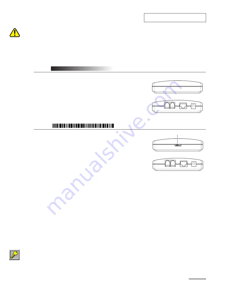
For analog telephone systems, use the Voice Center AT-101
Analog Interface shown at right (supplied with the Voice Center
Conference Phone), and follow the installation and operating
instructions that begin on page 4.

Digital

Digital telephone systems are usually found in corporate environments. 
Most PBXs (private branch exchanges) are digital. Signs that the
phone and line are digital: phones with multiple function keys and/or
multiple lines, the need to dial 9 for an outside line, no fax machines or
modems connected directly to the phone line. 

Caution:

if analog

equipment is connected directly to a digital telephone system, it will not
work, and the equipment can be damaged.

For digital telephone systems, use the Voice Center DT-102 Digital
Interface shown at right (sold separately from the Voice Center
Conference Phone). The Digital Interface is the same size and shape
as the Analog Telephone System Interface, but has different circuitry;
the Digital Interface can be identified by the 4-position switch on its
front side. For digital telephone systems, follow the installation and
operating instructions that begin on page 8.

4. Setup Tips 

• Choose an appropriate location for the Conference Phone. 

– Use the Conference Phone in an environment as free as possible from background noise. 
– To minimize echoes, position the conference phone at the center of the room, or at least

away from walls. 

– Avoid items that could cause noise or acoustic interference.

• Set up the Conference Phone following the instructions for the type of telephone system you are using:

– Instructions for an Analog Phone System begin on page 4.
– Instructions for a Digital Phone System begin on page 5.

• Make adjustments (as necessary) to obtain optimal acoustic performance.

Important:

The Voice Center Conference Phone's digital sound processing actively responds to

the acoustic environment. In small and/or reflective rooms, resonance (echoes) can cause
variable performance. Some small adjustments can dramatically improve results. See page 12
for tips to improve acoustic performance.

HANDSET

CONFERENCE

PHONE

DC 12V

PHONE

1

2

3

4

Front view

Rear view

DT-102 Digital Telephone 

System Interface

4-position switch

PHONE

CONFERENCE

PHONE

DC 12V

LINE

Front view

Rear view

AT-101 Analog Telephone

System Interface

Summary of Contents for Voice Center cp-2010

Page 1: ...Voice Center Conference Phone CP 2010 model series User s Manual...

Page 2: ......

Page 3: ...th Analog Telephone System 6 Operation with Analog Telephone System 7 Digital Telephone System Setup with Digital Telephone System 8 Keypad Functions with Digital Telephone System 10 Operation with Di...

Page 4: ...complete specifications see page 14 of this manual Quick Start Guide 1 Package Contents Check the package contents to confirm you have everything at hand For digital telephone systems the DT 102 Digit...

Page 5: ...e phone line Caution if analog equipment is connected directly to a digital telephone system it will not work and the equipment can be damaged For digital telephone systems use the Voice Center DT 102...

Page 6: ...east 20 inches 0 5 m from any wall and at least 6 inches 0 15 m from the edge of the table Plug the other end of the RJ 45 cable into the Analog Interface connector labeled Conference Phone 2 Connect...

Page 7: ...y connect a standard analog telephone to the Voice Center Analog Interface Plug a standard RJ 11 cable from the analog telephone into the connector in the Analog Interface labeled Phone The standard p...

Page 8: ...ther call pressing the FLASH key once more begins the three way call if you have subscribed to local telephone company s three way call service Standard 12 button Telephone Keypad 10 digits plus and U...

Page 9: ...ess the MUTE key again to turn on the microphones Ending a call Press the ON OFF key The green LED will extinguish Accessing special telephone service features These features are only available if you...

Page 10: ...it into the Digital Interface connector labeled Handset Plug one end of RJ 22 telephone handset cable supplied with the Digital Interface into the Digital Interface connector labeled Phone Plug the o...

Page 11: ...on switch level 1 is highest level 4 is lowest If the setting is too high for the digital telephone the party at the other end of the line may get noise feedback buzz tone or squeal if the setting is...

Page 12: ...em you must dial calls on the digital telephone connected to the DT 102 Digital Interface The standard 12 button telephone keypad REDIAL and FLASH keys do not function with most digital telephone syst...

Page 13: ...s pressing the volume keys adjusts the ringer volume The ringer volume setting is saved until adjusted again Placing a call 1 Pick up the digital telephone handset and dial the call 2 Press the ON OFF...

Page 14: ...o quality include plants cups and papers near the microphones Have speakers direct their voices toward the Conference Phone or if used External Microphone Speak at normal conversational volume To obta...

Page 15: ...nto one of the two microphone connectors on the underside of the Conference Phone the micro phone connectors are labeled EXTERNAL MIC 2 Place the external microphone at least 18 inches 0 5 m from the...

Page 16: ...3 internal microphones 47 4 dB Mechanical specifications Speakerphone main body 13 inch 33 cm diameter each arm extends 6 5 inch from the center 20 0 7 oz 567 20 g Comes with 20 ft 6 m RJ 45 cable Tel...

Page 17: ...Web site at www spracht com send an e mail to info spracht com or contact us at Spracht Tel 650 318 8061 Fax 650 318 8060 2672 Bayshore Parkway Bldg 900 Mountain View CA 94043 USA For repair or repla...

Page 18: ...cause harmful interfer ence to radio or television reception which can be determined by turning the equipment off and on the user is encouraged to try to connect the interference by one or more of the...

Page 19: ......

Page 20: ...ACHT Tel 650 318 8061 Fax 650 318 8060 2672 Bayshore Parkway Bldg 900 Mountain View CA 94043 USA www spracht com 2001 Spracht Spracht and Voice Center are trademarks of ODI SP1009 Rev 4 02 Made in Tai...

Reviews: