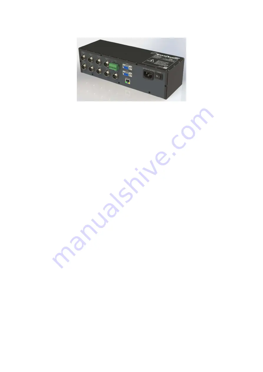
Sportdevices SP6 Installation And Setup Manual Download Page 1

SP6 Installation and Setup V0.91 


Sportdevices © 2019 


20/NOV/2019 

SP6 INSTALLATION AND SETUP MANUAL 


Contents 

1


S

portDevices End User Software License & Warranty Disclaimer ........................................ 2


2


General Safety Instructions

 .................................................................................................... 3


2.1


SAFETY: When Working Inside Your Device ............................................................. 3


2.2


SAFETY: General Power Safety ................................................................................ 4


2.3


SAFETY: If Your Device Gets Wet ............................................................................. 4


2.4


SAFETY: If You Drop or Damage Your Equipment ..................................................... 5


2.5


Protecting Against Electrostatic Discharge ................................................................. 5


2.6


Dynamometer Important Safety Tips

 .............................................................................. 6


2.7


Technical Specs

 ............................................................................................................ 6


2.7.1


Input Specs

 .............................................................................................................. 6


2.7.2


Output Specs

 ........................................................................................................... 7


2.7.3


Connectivity Specifications

 ........................................................................................ 7


3


SP6 Installation .................................................................................................................. 8


3.1


Introduction

 ................................................................................................................ 8


3.2


Dynamometer Installation.

 ............................................................................................ 8


3.2.1


Vehicle dynamometers

 ............................................................................................. 8


3.2.2


2WD single / double roller dynamometer

 .................................................................... 9


3.2.3


Single roller AWD dynamometer:

 ............................................................................. 10


3.2.4


Twin roller AWD dynamometer:

 ............................................................................... 11


3.2.5


HUB-2 Dynamometer

 .............................................................................................. 12


3.2.6


HUB-4 Dynamometer

 .............................................................................................. 13


3.2.7


Engine Test bed dyno installation

 ............................................................................. 14


3.3


Proposed installation parts.

 ......................................................................................... 15


3.4


SP6 Connections

 ........................................................................................................ 16


3.4.1


SP6 Front Panel

 ...................................................................................................... 16


3.4.2


SP6 Rear Panel

 ....................................................................................................... 18


4


SportDyno Quick Setup Guide

 .............................................................................................. 22


4.1


Inertial Configuration: Roller / Flywheel

 ........................................................................ 22


4.2


Ratio Configuration

 .................................................................................................... 23


4.3


Load Cell Calibration

 ................................................................................................... 24


4.4


Speed Control Configuration (SP4-SP6)

 ......................................................................... 25


Summary of Contents for SP6

Page 1: ...2 7 1 Input Specs 6 2 7 2 Output Specs 7 2 7 3 Connectivity Specifications 7 3 SP6 Installation 8 3 1 Introduction 8 3 2 Dynamometer Installation 8 3 2 1 Vehicle dynamometers 8 3 2 2 2WD single double roller dynamometer 9 3 2 3 Single roller AWD dynamometer 10 3 2 4 Twin roller AWD dynamometer 11 3 2 5 HUB 2 Dynamometer 12 3 2 6 HUB 4 Dynamometer 13 3 2 7 Engine Test bed dyno installation 14 3 3 P...

Page 2: ...irmware are licensed on a non transferable as is without warranty basis only There are no warranties which extend beyond those stated here The purchase price of any SPx kit SP1 SP3 SP4 SP6 includes an implicit software license This software license does not include any setup training calibration or other consulting services By installing and or using the Software you certify that you have read und...

Page 3: ...d on or tripped over When operating your equipment Do not use your equipment in a wet environment for example in a wet basement Do not use AC powered equipment during an electrical storm Do not spill food or liquids on your equipment Before you clean your equipment disconnect it from the electrical outlet Clean your device with a soft cloth dampened with water Do not use liquids or aerosol cleaner...

Page 4: ... for grounded plugs and plugged into a grounded wall outlet If you are using a multiple outlet power strip use caution when plugging the power cable into the power strip Some power strips may allow you to insert a plug incorrectly Incorrect insertion of the power plug could result in permanent damage to your equipment as well as risk of electric shock and or fire Ensure that the ground prong of th...

Page 5: ...duct specific safety information located on the Safety Information section of this website Electrostatic discharge ESD events can harm electronic components inside your device Under certain conditions ESD may build up on your body or an object such as a peripheral and then discharge into another object such as your device To prevent ESD damage you should discharge static electricity from your body...

Page 6: ...ical wires and boxes may be fatal Disconnect all power to the electrical system before inspecting or servicing During extended testing vehicle cooling system and engine may become very hot Extreme caution is necessary when working near these components Always inspect vehicle tires for wear or damage before testing and only operate with tires that are in good condition and at the proper tire pressu...

Page 7: ...ntrol Signal 0 5V 2 4 KHz fixed 10 bit 0 to 100 duty cycle 8 x Digital Outputs 12V Relays max 0 5 A sink max recommended 100 ma 1 x Air Speed Output PWM 0 5v 2 4 KHz fixed 10 bit 0 to 100 duty cycle 1 x Servo output Throttle Selectable from PWM 0 5v 10 bit or RC pulse type PPM 50 Hz 0 5 to 2 5 ms pulse 2 7 3 Connectivity Specifications 2 x RS232 DB9 Connector Computer and provision for serial Cons...

Page 8: ...cable as long as possible and USB part close to the computer Installation Cables Software CD 3 2 Dynamometer Installation Two basic types of dynamometers can be controlled with SP6 On vehicle dynamometers roller or hub SP6 performs basically data acquisition and speed control on the dynamometer roller s Normally SP6 is not used to control the vehicle operation as the operator can actuate directly ...

Page 9: ...l Exhaust Gas Analyzer 3 2 2 2WD single double roller dynamometer In 2WD dynamometers the main speed sensor F1 is recommended to be installed at the brake side For single roller dynamometers there is obviously only one sensor F1 one load cell F1 and one power supply brake while for twin roller dynamometers the rear sub axle could have its own auxiliary speed sensor connected to channel F2 if the d...

Page 10: ... AWD dynamometer In single roller AWD dynamometers each axle has its own hall sensor load cell and power supply brake using F1 and R1 channels as shown in the picture Note speed sensor is recommended to be mounted at brake side to avoid the oscillations caused by the elastic couplers ...

Page 11: ...nels are used roller and cell Optionally SP6 could use the same configuration as 2WD twin roller dynamometers roller channels F2 and R2 in order to measure speed at rear subaxes not braked even with the SP6 AWD version 2 load cells since the rear sub axles are not braked and do not need a load cell Note auxiliary sensors F2 and R2 are optional ...

Page 12: ...at only channels F1 and R1 are complete rollers F2 and R2 can be used for auxiliary rollers but cells F2 and R2 do not exist Thus when using the DAQ with a HUB 2 dynamometer only front and rear channels can be used then it is proposed to use Front 1 for left side and Rear 1 for right side This also happens with SP5 AWD Actually left and right channels are swappable ...

Page 13: ...4 Dynamometer HUB 4 Dynamometer can only be implemented using SP6 HUB 4 version since it is the only one that implements the 4 load cells and has the 4 brakes sync active HUB 2 version will not have it active In the next picture CAN IDs are shown to ease the PWS connections ...

Page 14: ...els F1 roller F1 and cell F1 will be used As SP6 2WD still have two load cell inputs this feature can be used to control 2 dynamometers with a single DAQ using two SportDyno profiles For instance a 2WD dynamometer with channels F1 and engine dynamometer with channels R1 but not at same time Note SP6 can be installed close to the dyno engine to shorten all data and control cables and then only the ...

Page 15: ...ke control by controlling the brake current Throttle Servo optional A high torque RC servo can be used to drive the throttle Ignition and Starter Relays engine test bed 12 volt relays to control the engine Additional relays can be controlled with the SP6 to control the fans on the room Fans Turbines Some type of fans or turbines may be necessary for the following functions o Feeding fresh air inta...

Page 16: ...data 250 Kbaud default 2 x RS232 Serial connector COM0 Computer 115200 baud no parity 1 stop bit COM1 provision for serial Console 1 x Ethernet Connector 100 Mbit 1 x Mains 230 VAC 36W Power Input SP6 also provides two leds Red led normally OFF If ON it means that there is some error at initialization If blinking it may mean that 12V power supply is faulty Green led normally shows the SP6 activity...

Page 17: ...is not recommended to be changed it will cause to lose communications with power supplies Please pay attention to the list because some units have an incorrect text in the panel Production Units Prototype Units 1 5V max 100 ma 1 GND 2 Shield 2 CANL 3 CANH 3 Shield 4 CANL 4 CANH 5 GND 5 5V max 100 ma 3 4 1 4 Engine RPM Input 1 GND 2 Engine RPM pulses 0 5 V 3 5V max 100 ma 3 4 1 5 USER CANBUS This C...

Page 18: ... are 8 Relay Outputs Each relay output consists of an Open Collector line and a 12 Volt Positive line which are intended to drive low power 12 volt relays 100 ohm approx The maximum power deliverable by the SP6 is 1 5A this means that low consumption relays should be used but they can be operated all at a time while SP5 had restrictions with the max number of relays Normally the terminals Normally...

Page 19: ...ow Speed counter CNT typically for detonation counter 1 12V 100 ma max 2 Input 0 5V max 1000 Hz 3 GND 3 4 2 5 Servo Output Servo Output is internally configurable to RC pulse PPM or PWM analog 1 6V 4A max 2 Output Configurable to PPM PWM analog 0 5V 3 GND 3 4 2 6 Air Speed Airspeed output PWM 0 5 volt 2 4 KHz as a function of roller speed 1 Output 0 5V configurable as PWM or analog 2 GND 3 4 2 7 A...

Page 20: ... get the brake control signal from the 5 pin connector Connect this cable if CAN is not available or not being used PWS3 x and HS PWS Recently we have added CANBUS to PWS3 x and HS PWS connect this to SP5 SP6 PWS CANBUS In case of several PWS AWD dyno or HUB 4 the last PWS in the bus must have the terminator ON the rest terminator OFF jumper removed It will be shown a C in the LCD close to the tem...

Page 21: ...ortdevices 2019 20 NOV 2019 PWS1 5 IMPORTANT Do not use 5V I P and GND lines these lines are not isolated from mains line and will cause severe damage to SP6 or computer They are only used for testing purposes non isolated potentiometer ...

Page 22: ...Cell configuration this process can be performed at the end Speed Control Configuration 4 1 Inertial Configuration Roller Flywheel Setup all roller dyno data at Config Class of Dyno Window Dynamometer type Vehicle Dyno or Engine testbed Roller Diameter Roller Inertia Number of Teeth for gear tooth Note recommended from 80 to 150 teeth Prescaler always 1 for SP6 please note that SP6 can internally ...

Page 23: ...amp Although Engine RPM Channel is not directly used for the three functions described below Sportdyno will perform an histogram from engine rpm and roller rpm channels to get the Ratio value before starting the test and by default after the test is finished Fixed ratio in certain cases when Ratio value is known ratio can be setup directly for instance engine test bed when there is a fixed transmi...

Page 24: ...calibration consists of applying a known weight on a calibration arm at the brake But first of all the cell has to be zeroed when it has no weight Then the program is able to use the difference from the digital reading between the no load condition and the loaded condition to perform the calibration ...

Page 25: ...ith a negative weight for instance 20 kg for a 20 kg weight 4 4 Speed Control Configuration SP4 SP6 P I D coefficients determine the brake response to the difference between the desired speed target and the current speed this difference is called error SP6 implements a standard PID with I constant proportionally to P Kp Ti this allows changing only Kp constant and SP6 will modify Ki to keep the sa...

Page 26: ... the integral control I is used Ti is normally modified in a narrow interval typically 0 5 to 1 5 to get a faster approaching drift to the target low values but fast approaching drift also cause to decrease the reaction speed Overshoot With high inertia dynos some overshoot will be present in the control operation but normally a small overshoot is preferred as it ensures faster control than no ove...

Reviews: