P. 6
© 2004 Sportcraft, Ltd.
3
2
4
5
31
31
34
34
32
32
9
9
14
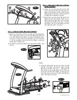
FIG. 2
33
33
30
35
30
35
8
8
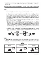
FIG. 3
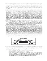
FIG. 3A
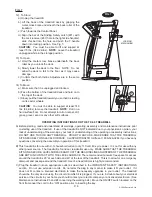
FIG. 4A
27
43
41
26
27
38
41
43
42
42
39
40
FIG. 4
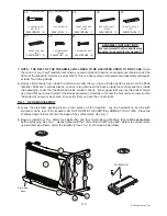
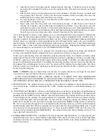
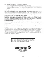
FIG. 2: SIDE RAIL TUBE AND CONTROL
PANEL ASSEMBLY
5) Attach the Left Side Hand Rail Tube (#5)
to the Left Vertical Arm (#7) with two 10 x
60mm Hex Bolts (#9) and two 10mm Spring
Washers (#32). See Fig. 2. Do the same for
the Right Side Hand Rail Tube (#4).
6) Attach the Front Hand Rail Tube (#3) to the
Side Rail Tubes (#4 and #5) using one 6 x
50mm Allen Key Bolt (#31) and one 6mm
Arched Washer (#34) at each end. Go back
and tighten, but do not overtighten, with the
5mm Allen Key (#14). See Fig. 2.
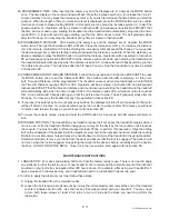
FIG. 3: CONTROL PANEL BRACKET ASSEMBLY
7) Attach the Control Panel (#2) to the Side Rail Tube Assembly.
from underneath using two Control Panel Brackets (#8), two
4 x 12mm Black Screws (#30), two 4mm Flat Washers (#33),
and four 4 x 16mm Tail Cut Screws (#35) per side. See Fig.
3. Do not overtighten the screws into the plastic, as you may
damage the Control Panel.
8) Connect the Control Panel Wire to the Control Panel (#2). See
Fig. 3A.
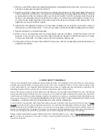
FIG. 4
9) Install the Right (#38 and #39) and the Left (#40
and #41) Foot Rails using two 6 x 25mm Screws
(#42) per Foot Rail. See Fig. 1. Next place the
Rear Roller Covers Right (#26) and Left (#27) by
the ends of the Rear Foot Rails, covering the rear
roller and secure using one 6 x 20mm Bolt (#43) per
cover. See figures 4 and 4A


