P. 10
© 2004 Sportcraft, Ltd.
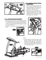
4. Insert the short end of the Allen wrench provided into the bolt head. If the belt is too far to the right
as looking at the treadmill from the rear, use the right side bolt. If the belt is too far left, use the left
side bolt.
5. With the belt running, turn the Allen wrench 1/2 turn clockwise. Observe the belt. It should start
moving away from the side. Turning the bolt head clockwise (either bolt head) will cause the
walking belt to move away from the bolt you are turning.
6. You may repeat the 1⁄2 turn two (2) more times for a total of three 1⁄2 turns. Allow some time, at least
30 seconds for the belt to move.
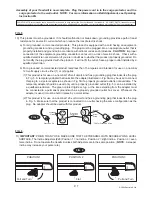
7. Never make more than three half turns of the same bolt head. If, after three 1⁄2 turns the belt
remains out of position, use the other side for adjustment as follows: If you have been using the
right side bolt, move to the left side. Turn the bolt counterclockwise 1⁄2 turn. (See illustration above.)
Turning the bolt head counterclockwise (either bolt head) will cause the walking belt to move toward
the bolt you are turning. Allow some time, at least 30 seconds for the belt to move.
If your belt appears to slip as you are walking on it, you should tighten the belt somewhat to eliminate the
slip. Follow the instructions above EXCEPT make an equal number of adjustment turns on EACH bolt. It
may take a number of complete revolutions to tighten your belt. Turning the bolt heads clockwise will tighten
the belt. Make one complete revolution adjustment to each bolt head and then walk on the your treadmill to
test for slipping. If it still slips, repeat the operation. After making 2 complete turns of each bolt and slipping
still occurs, make 1⁄2 turns in each bolt and test after each side is adjusted. Adjusting the walking belt too tight
can cause damage to your treadmill. FOLLOW THESE INSTRUCTIONS.
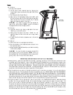
I) PULSE MODE. The pulse sensor is on whenever the red safety key is inserted. For safety and enhanced
accuracy, the treadmill should be stopped whenever you place your finger on the pulse sensor.
To take your pulse reading, stop your treadmill by pressing the stop button. Your distance and time values
will be saved. Place one foot on each siderail and remain as still as you possibly can. Place your index finger
OVER the pulse lens. Three bars should appear within a few seconds. In addition, the upper left side LED
above the left-hand window will light. This signals that the pulse reading is eminent. Two seconds after the
bars appear they will disappear one at a time. The sensor will then display the average pulse rate. Once
finished, re-start your treadmill by resetting your speed value as instructed in #E or complete your workout
by removing the safety key.
NOTE
: 1)
DO NOT
press your finger firmly onto the lens. Too much pressure on your finger tip, movement
of your hand or body will result in the wrong reading or no reading at all.
2) THE PULSE SENSOR IS NOT A MEDICAL DEVICE. IT IS MEANT FOR YOUR INFORMATION
PURPOSES ONLY AND IS DESIGNED TO GIVE AN “AVERAGE” PULSE RATE. IT IS NOT INTENDED TO
OFFER MEDICAL ADVICE NOR WILL IT MEASURE PULSE ACCURATELY EVERY TIME.
J) CALORIE BURN. The calories burned during the current workout are displayed in the left-hand window of
the control console. It will show values from 001 to 999. Calories expended are controlled by distance, not
speed.
K) STOPPING THE TREADMILL. When you are finished with your workout or at any time during the workout,
you may stop the treadmill in a number of ways: A) Depress and release the STOP button. The treadmill will
gradually slow to 00.0MPH and the distance covered and calories burned during that workout will continue
to be displayed on the console. The values will stay for 30 minutes. After 30 minutes, all values will clear
and you must start again with instruction #D. You can clear the values by pressing and holding the STOP
button for 5 seconds. You can then start the treadmill by pressing the SPEED increase button in Instruction
#E. B) You may reduce the speed to zero by depressing the decrease symbol (-) until the right-hand speed
readout window reads 00.0. When you release the decrease button the treadmill will gradually stop. You will
have the same 30-minute options as stated above. C) You may pull the SAFETY KEY out of the slot in the
console and the treadmill will stop IMMEDIATELY. No values will be saved and all displays will be off. You
may restart with Instruction #D.
L) PROGRAMMED OPERATION. In addition to the manual operation described above, you may program your
treadmill workout to cover a certain distance regardless of time spent, a certain amount of time regardless
of distance covered or a combination of distance and time where the first value achieved (distance or time)
will end the workout.


