


Customer Service 1-888-707-1880
Dyaco Canada Inc. 2014
Email:
8
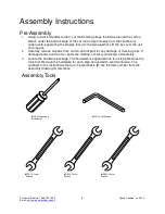
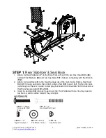
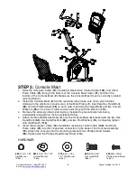
STEP 2:
Console Mast
1.
Slide the Computer Cable (
44
), Handlebar Resistance Control Cable (
148
), and Hand
Pulse Cable (
45
) through the bottom of the Console Mast Cover (
31
) and then the
bottom of the Console Mast (
2
). Make sure the Console Mast Cover is correctly oriented
(see illustration).
2.
Install the Console Mast (
2
) into the receiving tube (make sure not to pinch cables;
damage to the electronics could occur) of the Main Frame (
1
). Insert two Hex Head Bolts
(
68
) and two Flat Washers (
76
) on each side. Insert two Hex Head Bolts and two Curved
Washers (
83
) on the front. Tighten all six bolts firmly with the Wrench (
112
).
3.
Remove the white styrofoam pad (factor y installed to prevent bolts from being
accidentally dropped into the Console Mast Tube).
4.
Attach the Handle Bar Assembly (
3
) onto the Console Mast (
2
) bracket with the two Hex
Head Bolts (
68
), two Split Washers (
82
), and two Flat Washers (
76
). Completely tighten
with the Wrench (
112
).
5.
Insert the Computer Cable (
44
), Handlebar resistance control cable (
148
), and Hand
Pulse Cable (
45
) into their respective connectors in the back of the Console Assembly
(
19
). Attach the console onto the mounting plate with four Phillips Head Screws
(
99
).Tighten with the Phillips Head Screw Driver (
114
).
HARDWAR
#82.
5/16” x 1.5T
Split Washer
(2 pcs)
#83.
5/16” x 19 x 1.5T
Cur ved Washer
(2 pcs)
#76.
5/16” x 18 x
1.5T Flat Washer
(6 pcs)
#68.
5/16” x 5/8”
Hex Head Bolt
(8pcs)
#99.
M5 x 12mm
Phillips Head Screw
(4 pcs)


