Spirax Sarco TD120 Installation And Maintenance Instructions Manual Download Page 5

IM-P150-07 

 ST Issue 4

5

2. General product information

2.1  General description

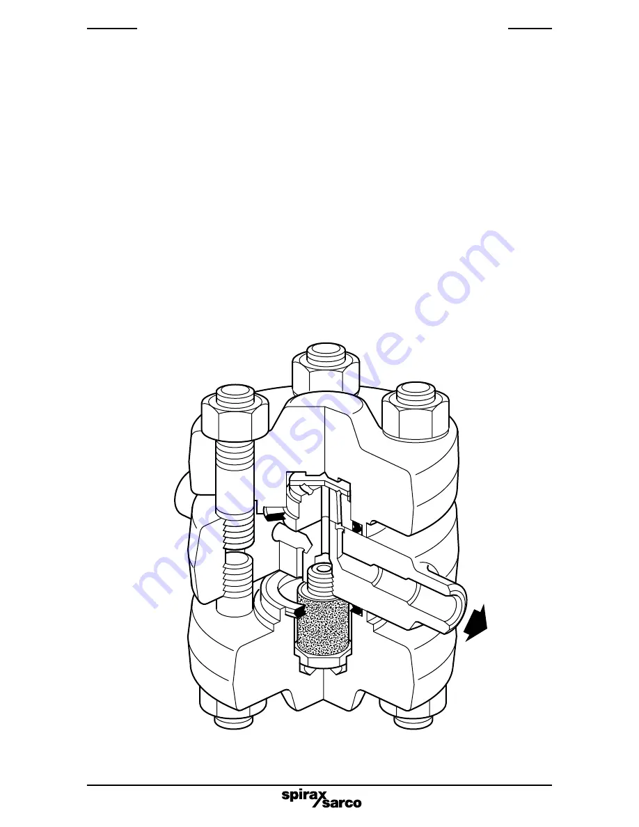
The TD120 is a maintainable medium high pressure thermodynamic steam trap with integral 
strainer  designed  specifically  for  steam  mains  drainage  applications  up  to  250  bar  g 
(3 625 psi g).

Standards

This  product  fully  complies  with  the  requirements  of  the  European  Pressure  Equipment 
Directive 97/ 23 / EC.

Certification

This product is available with certification to EN 10204 3.2. 

Note:

 All certification / inspection 

requirements must be stated at the time of order placement.

Note:

 For additional information see Technical Information Sheet TI-P150-01.

2.2  Sizes and pipe connections

½

", 

¾

" and 1" Butt weld ends to suit Schedule 160 pipe.

½

", 

¾

" and 1" Socket weld ends to ANSI B 16.11 Class 6000.

DN15  and  DN25  standard  integral  flange DIN 2549 PN250.

DN15,  DN20  and  DN25  standard  integral  flanges:  ANSI  600,  ANSI  900,  ANSI  1500, 

DIN  2547  PN100  and  DIN  2548  PN160.

Fig. 1  Thermodynamic steam trap

Summary of Contents for TD120

Page 1: ...ic Steam Trap Installation and Maintenance Instructions IM P150 07 ST Issue 4 1500050 4 1 Safety information 2 General product information 3 Installation 4 Commissioning 5 Operation 6 Maintenance 7 Spare parts Printed in the UK Copyright 2007 ...

Page 2: ...fically designed for use on steam air or condensate water which is in Group 2 of the above mentioned Pressure Equipment Directive The products use on other fluids may be possible but if this is contemplated Spirax Sarco should be contacted to confirm the suitability of the product for the application being considered ii Check material suitability pressure and temperature and their maximum and minimu...

Page 3: ...hocks 1 7 Pressure systems Ensure that any pressure is isolated and safely vented to atmospheric pressure Consider double isolation double block and bleed and the locking or labelling of closed valves Do not assume that the system has depressurised even when the pressure gauge indicates zero 1 8 Temperature Allow time for temperature to normalise after isolation to avoid danger of burns 1 9 Tools ...

Page 4: ...e product from an installation refer to Maintenance instructions 1 14 Freezing Provision must be made to protect products which are not self draining against frost damage in environments where they may be exposed to temperatures below freezing point 1 15 Disposal Unless otherwise stated in the Installation and Maintenance Instructions this product is recyclable and no ecological hazard is anticipa...

Page 5: ... 23 EC Certification This product is available with certification to EN 10204 3 2 Note All certification inspection requirements must be stated at the time of order placement Note For additional information see Technical Information Sheet TI P150 01 2 2 Sizes and pipe connections and 1 Butt weld ends to suit Schedule 160 pipe and 1 Socket weld ends to ANSI B 16 11 Class 6000 DN15 and DN25 standard...

Page 6: ...bar g 522 C 3626 psi g 972 F TMA Maximum allowable temperature 550 C 153 bar g 1022 F 2220 psi g Minimum allowable temperature 29 C 20 F PMO Maximum operating pressure 250 bar g 3626 psi g for saturated steam service TMO Maximum operating temperature 550 C 153 bar g 1022 F 2220 psi g Minimum operating temperature 0 C 32 F Note For lower operating temperatures consult Spirax Sarco PMOB Maximum oper...

Page 7: ... leg preceding the trap Access for removal of the integral strainer screen should also be provided 3 5 Suitable isolation valves must be installed to allow for safe maintenance and trap replacement Where the trap discharges into a closed return system a non return valve should be fitted downstream to prevent flow 3 6 Always open isolation valves slowly until normal operating conditions are achieved ...

Page 8: ...ference to venting air Initial start up can take several hours or days to bring the system to normal operating pressure and temperature Even if the trap has replaced another trap while the main system has remained running it may still be necessary to vent air from the drop leg If the trap is some distance from stop valve A Figure 2 it could be possible to air lock the pipework between valve A and ...

Page 9: ...Stop valve A Stop valve B TD120 Strainer Optional Dirt pocket dirt leg To drain or return To drain or return Fig 2 Typical installation Alternative layout Suggested drop leg if the TD120 is located more than 2 m 6 away from the main drop leg To drain ...

Page 10: ...ng torques see Table 1 After 24 hours in service and when reassembling the nuts should be tightened in a diagonally opposite sequence Open the isolation valves slowly until normal operating conditions are achieved Check for leaks 6 2 How to clean or replace the strainer Access to the strainer screen can be obtained by undoing the nuts 8 and removing the bottom cover Remove the strainer screen 4 Fi...

Page 11: ...IM P150 07 ST Issue 4 11 Table 1 Recommended tightening torques or Item Part N m lbf ft mm 4 22 A F 25 35 18 26 8 Nut 23 A F M16 160 180 118 132 8 Stud M16 85 90 62 5 66 8 2 6 7 7 4 8 Fig 3 ...

Page 12: ... Set of internals 2 7 2 off 4 Strainer screen 4 7 Set of cover gaskets 7 2 off Set of cover studs and nuts 8 8 off 9 How to order spares Always order spares by using the description given in the column headed Available spares and state the size and type of trap Example 1 Strainer screen for a Spirax Sarco DN15 TD120 thermodynamic steam trap Fig 3 8 8 4 7 2 7 8 8 ...

Reviews: