


IM-S24-42
CTLS Issue 10
23
300
250
200
150
100
50
0
-29
572
500
400
300
200
100
0
-20
0
4 8
12 16
0 50 100 150 200 232
425
400
300
200
100
0
-29
797
600
400
200
0
-20
0
5 10 15 19.6
0 50 100 150 200 250 284
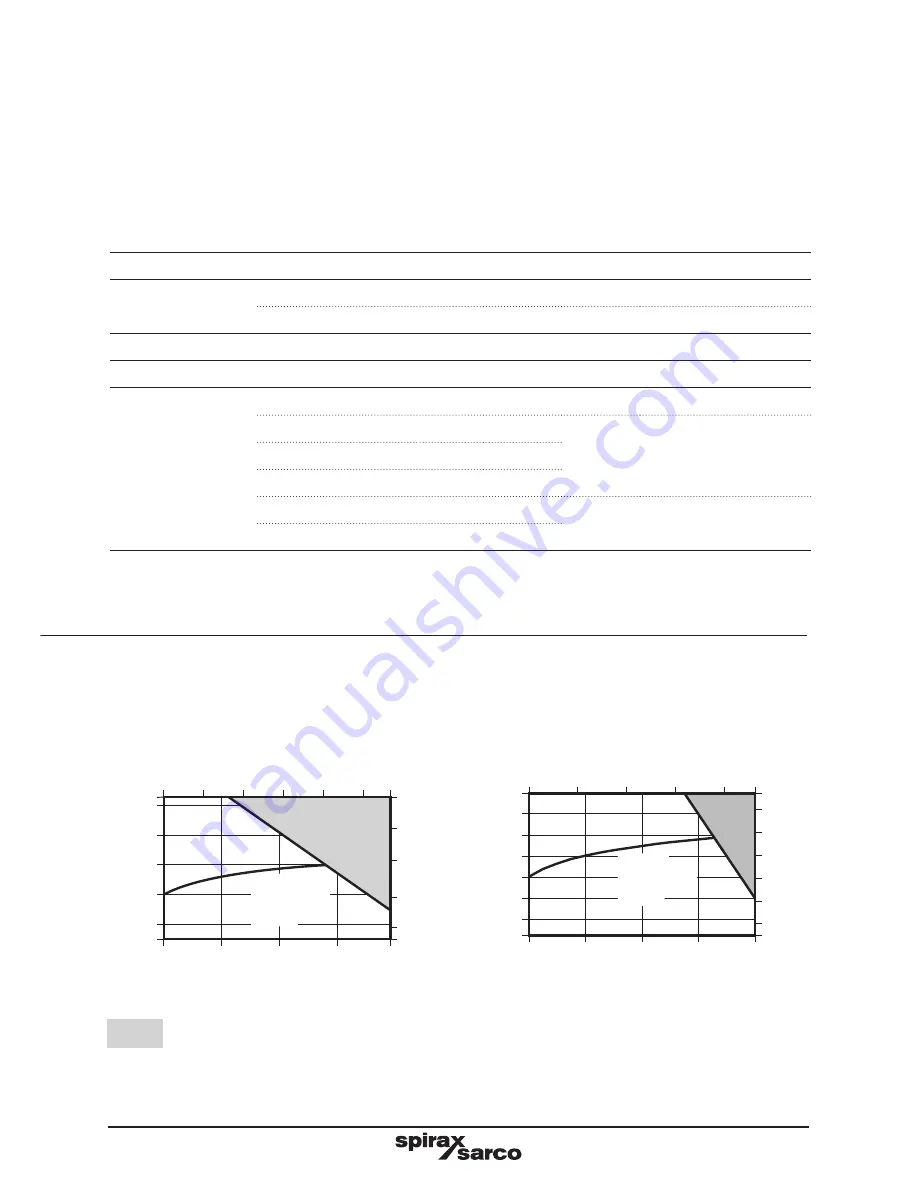
Bellows C
Bellows D
Te
mp
er
atu
re
°C
Pressure bar g
Te
mp
er
atu
re
°C
Pressure bar g
Pressure bar g
Pressure bar g
Te
mp
era
tu
re
°F
Te
mp
era
tu
re
°F
Steam
saturation
curve
Steam
saturation
curve
The product
must not
be used in this region.
Notes:
1.
Where the process fluid temperature is sub-zero and the ambient temperature is below +5 °C (41 °F),
the external moving parts of the valve and actuator must be heat traced to maintain normal operation.
2.
When selecting a valve with a bellows sealed bonnet, the pressure/temperature limits of the bellows
must be read in conjunction with the valve pressure/temperature limits shown above.
3.
As standard the KEA, KFA, KLA series two-port control valves are supplied with the PTFE stem sealing
option.
Body design conditions
ASME 150 and ASME 300
Maximum design
pressure
ASME 150 (6" to 12" only)
19.6 bar g @ 38
°C
(284 psi g @ 100
°F)
ASME 300
51.1 bar g @ 38
°C
(740 psi g @ 100
°F)
Maximum design temperature
425
°C
(800
°F)
Minimum design temperature
-29
°C
(-20
°F)
Maximum operating
temperature
PTFE soft seat (G)
200
°C
(392
°F)
Standard packing PTFE chevron
250
°C
(482
°F)
PEEK seat (K and P)
Extended bonnet (E) with PTFE chevron
Graphite packing (H)
425
°C
(800
°F)
Extended bonnet (E) with graphite packing
Note:
We recommend that an extended bonnet (E) with graphite packing is used where valve operation is
above 300
°C (572
°F).
Summary of Contents for Spira-trol K Series
Page 2: ...IM S24 42 CTLS Issue 10 2...
Page 53: ...IM S24 42 CTLS Issue 10 53 Fig 22 Balanced 3 19 4 6 16 31 Fig 21 15...
Page 57: ...IM S24 42 CTLS Issue 10 57 C1 C D1 D2 D B E G A H Soft seat arrangement C2 Fig 26 H1...
Page 61: ...IM S24 42 CTLS Issue 10 61 C2 B D4 D5 E G D F A H Soft seat arrangement Fig 28 H1...
Page 66: ...IM S24 42 CTLS Issue 10 66...
Page 67: ...IM S24 42 CTLS Issue 10 67...
Page 68: ...IM S24 42 CTLS Issue 10 68...


