Spirax Sarco LCS3050 Installation And Maintenance Instructions Manual Download Page 5

IM-P693-06 

EMM Issue 1

5

LCS3050 Low Water Level Switch for two probes

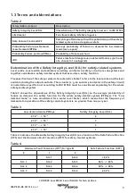
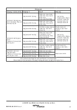
1.3 Terms and abbreviations

Table 2

Terms/Abbreviations

Description

Safety Integrity Level/SIL

Classification of the Safety Integrity Level acc. to IEC 61508

Lifetime (a)

Functional safety: Lifetime in years

Safe Failure Fraction/SFF

Percentage of failures without the potential to put the safety-

related system into a dangerous state

Probability Failure per Demand 

(Low Demand)/PFDav

Average probability of failure on demand for low demand 

mode (once a year)

Probability Failure per Hour/PFHav

Probability of failure per hour

DU

Failure rate for all dangerous undetected failures (per hour) 

of a channel of a subsystem


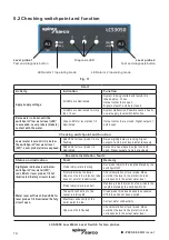
Determination of the Safety Integrity Level (SIL) for safety-related systems

Level probe, level switch and actuators (auxiliary contactor in safety circuit) are subsystems and 

together constitute a safety-related system that executes a safety function.

The specification of the safety-related characteristics Table 1 refers to the level probe and the level 

switch including the output contacts. The actuator (e. g. an auxiliary contactor in the safety circuit) 

is installation specific and, according to IEC 61508, must be considered separately for the whole 

safety-related system.

Table 3 shows the dependence of the Safety Integrity Level (SIL) on the average probability of 

failure on demand of a safety function for the whole safety-related system (PFDsys). The “Low 

demand mode” is here considered for a water level limiter, which means that the frequency of 

demands for operation of the safety-related system is no greater than one per year.

Table 3

Low demand mode PFDsys

Safety Integrity Level (SIL)

≥ 10

 -5

 ... < 10

 -4

4

≥ 10

 -4

 ... < 10

 -3

3

≥ 10

 -3

 ... < 10

 -2

2

≥ 10

 -2

 ... < 10

 -1

1

Table  4 indicates the attainable Safety Integrity Level (SIL) as a function of the Safe Failure Fraction 

(SFF) and the Hardware Fault Tolerance (HFT) for safety-related systems.

Table 4

Hardware Fault Tolerance (HFT) for type B

Safe Failure Fraction (SFF)

0

1

2

SIL 1

SIL 2

< 60 %

SIL 1

SIL 2

SIL 3

60 % - < 90 %

SIL 2

SIL 3

SIL 4

90 % - < 99 %

SIL 3

SIL 4

SIL 4

≥ 99 %

Summary of Contents for LCS3050

Page 1: ...r two probes Installation and Maintenance Instructions IM P693 06 EMM Issue 1 850146 00 1 Safety information 2 General product information 3 Mechanical installation 4 Electrical installation 5 Commiss...

Page 2: ...IM P693 06 EMM Issue 1 2 LCS3050 Low Water Level Switch for two probes...

Page 3: ...obe LP40 are EU type approved according to EN 12952 EN 12953 These Directives state among other things the requirements made on limiting systems and equipment for steam boiler plants and pressurised h...

Page 4: ...P40 LCS3050 corresponds to a type B subsystem with Safety Integrity Level SIL 3 Type B means that the behaviour under fault conditions of the used components cannot be completely determined The functi...

Page 5: ...tion The specification of the safety related characteristics Table 1 refers to the level probe and the level switch including the output contacts The actuator e g an auxiliary contactor in the safety...

Page 6: ...probe LP40 After the de energizing delay has elapsed the two output contacts of the level switch will open the safety circuit for the heating The switching off of the heating is interlocked in the ex...

Page 7: ...ixing screws cross recess head screws M3 4 Code switch for switching on off level probe 1 2 5 Code switch for switching on off level probe 1 2 6 Enclosure 7 Supporting rail type TH 35 EN 60715 Fig 2 T...

Page 8: ...eur de niveau 20 29 21 30 3sec Functional safety IEC 61508 SIL 3 10 S cm 9 2 LP 40 1 2 3 1 3 4 5 10 11 12 13 16 17 23 24 26 27 LCS3050 MIN 24 V 20 M 0 5A 4 393313 02 MADE IN GERMANY See installation i...

Page 9: ...00 mA semiconductor output 3 Safety circuit input and output 4 Wire link on site when used as water level limiter according to EN 12952 EN 12953 5 CEP Central earthing point in control cabinet 6 Level...

Page 10: ...tch for two probes Item 1 Level probe s LP40 2 Level switch LCS3050 3 Safety circuit 4 Level switch LCS3050 for low level pre alarm 4 2 Schematic representations of arrangements Fig 5 Fig 6 Fig 7 Fig...

Page 11: ...CS3050 as water level limiter The level switch opens two separate safety circuits Functional safety IEC 61508 SIL 3 Further applications in accordance with national sets of regulations Fig 8 Combinati...

Page 12: ...and 26 Provide the output contacts with a 2 A or 1 A for 72 hours operation slow blow fuse Note In the event of an alarm the level switch LCS3050 does not interlock automatically If a lock function i...

Page 13: ...g in case of emergency operation change the settings as follows Switch off supply voltage Unscrew the right and left fixing screws 3 and remove the lower terminal strip 2 Fig 2 Depending on which pro...

Page 14: ...ng Signal outputs 1 and 2 are closed instantaneously Red LEDs for level probe 1 2 illuminated Delay time has elapsed output contacts open Signal outputs 1 and 2 are closed Possible installation faults...

Page 15: ...LEDs for level probe 1 2 are flashing De energizing delay is running Signal outputs 1 2 are closed instantaneously Red LEDs for level probe 1 2 illuminated Delay time has elapsed output contacts open...

Page 16: ...r of level probes used Fault indication Status Diagnosis Function Next activity Faulty evaluation of level probe 1 channel 1 Diagnosis LED 1 and LED alarm 1 illuminated Output contacts are opened inst...

Page 17: ...and hold down key AL2 Diagnosis LED 1 flashing Malfunction in level probe 2 malfunction in level switch faulty wiring faulty measuring voltage check wiring measure probe voltages clean and if necessa...

Page 18: ...erve Figure 13 U2 4 10 12 U3 4 11 12 U2 3 10 11 immersed exposed Malfunction immersed alarm 0 7 V 85 Hz U2 4 10 12 U2 4 10 12 U3 4 11 12 2 2 Item 1 CEP Central earthing point in control cabinet 2 Leve...

Page 19: ...ing on which probe shall be deactivated set S1 or S2 of code switches 4 and 5 to ON Attach lower terminal strip and fasten fixing screws Apply supply voltage equipment is re started 4 Toggle switch wh...

Page 20: ...circuit The circuitry must meet the requirements of the EN 50156 6 6 Checking the switchpoints To check the switchpoint Low water LW you have to lower the water level When the water level falls below...

Page 21: ...ignalling 24 Vdc max 100 mA semiconductor output Indicators and adjustors 2 buttons for test and diagnosis 2 red green LEDs for indicating the operating mode and alarm 3 red LEDs for diagnosis 2 two p...

Page 22: ...eration 24 hours Relative humidity max 95 no moisture condensation Site altitude max 2000 m Approvals EU type approval PED Pressure Equipment Directive 2014 68 EU EN 12952 11 EN 12953 09 Requirements...

Page 23: ...x Sarco representative Ensure all items are suitably packed for transit preferably in the original cartons Please provide the following information with any equipment being returned 1 Your name compan...

Page 24: ...IM P693 06 EMM Issue 1 24 LCS3050 Low Water Level Switch for two probes Spirax Sarco Ltd Runnings Road Cheltenham GL51 9NQ United Kingdom www spiraxsarco com...

Reviews: