


IM-P693-06
EMM Issue 1
12
LCS3050 Low Water Level Switch for two probes
4.5 Connection of level probe
To connect the level probe please use screened multi-core control cable, min. conductor size 0.5 mm
2
, e.g.
LiYCY 4 x 0.5 mm
2
, max. length 100 m.
Wire terminal strip in accordance with the wiring diagram. Fig. 4. Connect screens to terminals 5 and 13 and
to the central earthing point (CEP) in the control cabinet.
4.6 Connection for signal output
A signal output for the connection of further external signalling equipment is allocated to each monitoring
channel in the level switch, max. load 100 mA. For connecting the level switch with the signal output unit
use a control cable, 2 x 0.5 mm
2
. In the event of an alarm or error message the signal outputs (terminals 20,
21 and 29, 30) close instantaneously.
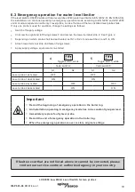
4.7 Connection of safety circuit
Connect the safety circuit for the heating to terminals 23, 24 and 26, 27. When used as water level limiter
according to EN 12952 / EN 12953, connect the output contacts of the two monitoring channels by adding
a wire link between the terminals 24 and 26.
Provide the output contacts with a 2 A o r
1 A (for 72 hours operation) slow-blow fuse.
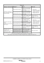
Note
In the event of an alarm the level switch LCS3050 does not interlock automatically. If a
lock function is required by the installation it must be provided in the follow-up circuitry
(safety circuit). The circuitry must meet the requirements of the EN 50156.
Important
-
Provide the level switch LCS3050 with an external semi-delay fuse 0.5 A.
-
Connect screens to terminals 5 and 13 and to the central earthing point (CEP) in
the control cabinet.
-
To protect the switching contacts provide the safety circuit with a slow-blow fuse
2 A or 1.0 A (for 72 hrs. operation acc. to TRD 604).
-
When switching off inductive loads, voltage spikes are produced that may impair
the operation of control and measuring systems. Connected inductive loads
must be provided with suppressors such as RC combinations as specified by
the manufacturer.
-
When used as water level limiter according to EN 12952 / EN 12953 connect
terminals 24 and 26 by adding a wire link.
-
Install connecting lines to level probes and logic unit separated from power cables.
-
Do not use unused terminals as support point terminals.
4.8 Tools
Screwdriver for slotted screws, size 3.5 x 100 mm, completely insulated according to VDE 0680-1.