


IM-P693-06
EMM Issue 1
4
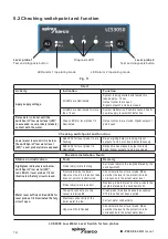
LCS3050 Low Water Level Switch for two probes
Note
The level probe LP40 is a simple item of electrical equipment as specified in EN 60079-
11 section 5.7. According to the European Directive 2014/34/EU the equipment must be
equipped with approved Zener barriers if used in potentially explosive areas. Applicable
in Ex-zones 1, 2 (1999/92/EC).
The equipment does not bear an Ex marking.
Note
: The requirements of the IEC 61508 are not met if the LP40 + Zener ba
LCS3050 are interconnected!
1.2 Functional Safety according to IEC 61508
Safety characteristics of the subsystem LP40/LCS3050
The level switch LCS3050 is certified acc. to IEC 61508 if used in combination with level
probe LP40.
The combination LP40/LCS3050 corresponds to a type B subsystem with Safety Integrity Level
(SIL) 3. Type B means that the behaviour under fault conditions of the used components cannot
be completely determined. The functional safety of the equipment combination refers to the
detection and evaluation of the water level and, as a consequence, the contact position of the
output relays.
The design of the equipment combination LP40/LCS3050 corresponds to the architecture 1oo2.
This architecture consists of two channels that detect and diagnose faults in each other. If a fault
is detected, the equipment combination LP40/LCS3050 will go to the safe state, which means that
the contacts of both output relays will open the safety circuit.
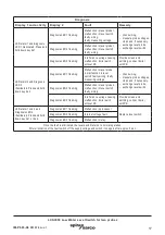
Table 1
Safety characteristics
SIL
Architecture
Lifetime (a)
Proof Test
Interval (a)
General
3
1oo2
20
20
SFF
PFDav
PFHav
λ DU
Level switch LCS3050 in
conjunction with two level
probes LP40
>90%
<5 x 10
-4
<5 x 10
-8
<10 x 10
-8