background image

Page 09

4 - Operation

4.1 - Protective Guard

4.2.1

4.2.2

4.2.3

4.2.4

4.2.5

4.2.6

4.2.7

CAUTION:  DRILL BITS MAY BE HOT AFTER USE.  ALLOW DRILL BITS TO COOL 

DOWN BEFORE TOUCHING.
BEFORE REMOVING OR  INSTALLING THE DRILL BITS, DISCONNECT OR 

LOCK-OUT THE POWER SUPPLY TO THE DRILL MOTOR.

4.2 - Drill Bit Removal and Installation

Diagram 4-10

4.1.1

4.1.2

We recommend using a piece of card stock on the Table when 

leveling the drill bit to avoid drilling into the drill strip.  This will 

lengthen the life of your drill bits and keep them sharper.

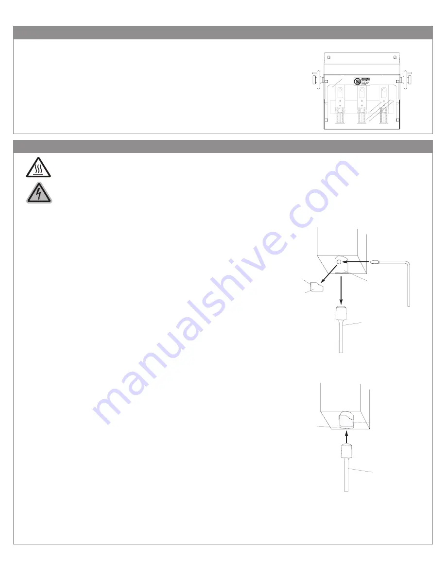
Remove the hole guard which is attached to the chuck.  This is 

done by grasping the tab and sliding the guard off.

Using the Chuck Release Key (EBM-32), insert the tapered end 

facing down into the chuck hole.  In a clockwise motion turn the 

Chuck Release Key 45 degrees.  The drill bit will slide out of the 

chuck.  It is recommended that you hold onto the drill bit so that it 

does not drop out of the chuck damaging the tip.

To install a drill bit, grasp the drill bit, and being careful to keep it 

straight, press it up into the chuck.

Seat the drill bit by using a stack of scrap paper.  Set the scrap on 

the table.  Lower the table lift speed by turning the Table Adjust-

ment Knob (see section 4.9).  Step on the foot pedal slowly rais-

ing the table toward the Drill Bit.  Put light pressure on the hollow 

Drill Bit seating it firmly in place.  

Remove the scrap paper and turn the machine on to check the 

concentricity of the bit.  If the bit is not concentric, remove it and 

repeat steps 4.2.2 through 4.2.5 until it is concentric.  

When the drill bit is correctly installed replace the hole guard back 

onto the chuck to protect debris from clogging the chuck.

Diagram 4-20

Chuck

Hole Guard

Drill Bit

Chuck Release Key

Tab

Chuck

Hole Guard

Drill Bit

Diagram 4-30

Your FMMH-3.1 comes with a protective guard installed.  DO NOT 

operate this machine without the guard in place.  

Please note that when you are performing certain operations such 

as removing and installing drill bits, you will need to move the 

guard out of the way.  Making sure the power to the machine is 

disconnected or locked-out, push the guard up and hold in place 

while performing necessary operations or maintenance.  The pro-

tective guard should not be removed during operation.

Summary of Contents for FMMH 3.1

Page 1: ...se operating instructions for future reference 485 Hague Street Rochester NY 14606 U S A Tel 585 436 1934 Fax 585 464 8665 www lasscowizer com info lasscowizer com Serial Number Date of Purchase Deale...

Page 2: ...g the Drill Bits Adjusting the Back Gauge Assembly Adjusting the Distance Between Heads Drilling Procedures Tips on Drilling 5 Maintenance 5 1 5 2 5 3 5 4 Page 13 Page 13 Page 14 Page 15 Safety Annual...

Page 3: ...NED FOR ONE PERSON OP ERATION Never operate the machine with more than one person KEEP CHILDREN AWAY All visitors should be kept a safe distance from the work area MAKE WORKSHOP KID PROOF with padlock...

Page 4: ...2 Safety 2 2 Warning Labels Page 03 WARNING DO NOT EXPOSE TO RAIN OR USE IN DAMP LOCATIONS...

Page 5: ...onnect the equipment grounding conductor to a live terminal Check with a QUALIFIED ELECTRICIAN or service personnel if the grounding instruc tions are not completely understood or if in doubt as to wh...

Page 6: ...1 FMM6 652A Chip Bag Assembly 1 MS 1 Drill Sharpener 1 FMM6 651A Master Chip Chute 1 this item may be installed HEX 732 T Hex Wrench 7 32 T Style 1 HEX 18 Hex Wrench 1 8 1 FM4 4007 Side Stop Screws 4...

Page 7: ...machine down in its desired location and determine if the machine is level making sure that it does NOT rock in any direc tion If it does determine which Leveling Feet need to be adjusted and whether...

Page 8: ...making sure it is sealed securly Replace the Back Cover by securing the eight 8 hex screws that hold it in place After adding the oil it will be necessary to work the air out of the system This is do...

Page 9: ...ty this bag as needed to avoid clogging Master Chip Chute Chip Bag Table Paper Side Stop Side Stop Screws 3 8 Electrical Instructions 3 8 1 3 8 2 Your FMMH 3 1 comes with an electrical cord containing...

Page 10: ...ght press it up into the chuck Seat the drill bit by using a stack of scrap paper Set the scrap on the table Lower the table lift speed by turning the Table Adjust ment Knob see section 4 9 Step on th...

Page 11: ...T loosen the insert retainer screw approximately one half turn loosening too much may cause the insert retainer screw to come out com pletely Retighten the insert retainer screw until it is snug but n...

Page 12: ...b Back Gauge Table Back Gauge Scale Back Gauge Scale Back Gauge Scale Drill Strip Drill Strip Hollow Drill Bits 4 5 Adjusting the Distance Between Heads 4 5 1 4 5 2 4 5 3 To adjust the outside spindle...

Page 13: ...t to be drilled on the table and make sure it is secure using the Paper Side Stops To drill step down on the Foot Pedal and hold raising the Table up to meet the drill bits Make sure the Table rises f...

Page 14: ...ter clockwise Turn the Hand Wheels until the slot at the inside end of the wheel is facing straight up Remove the Hand Wheels Remove the two 2 1 8 button head screws and the washers that they secure i...

Page 15: ...ween the two pulleys and measure the distance between the straight edge and the belt depression The belts can be adjusted by loosening the Lock Nut on the Belt Adjustment Screw located on the front po...

Page 16: ...break down when their temperature exceeds 120 F 48 9 C Hydrol HL will maintain its consistency until it reaches 210 F 98 9 C Access the Oil Tank by removing the eight 8 hex screws on the rear of the m...

Page 17: ...uring the eight 8 hex screws that hold it in place After changing the oil it will be necessary to work the air out of the system This is done by turning the power to the Hydraulic Motor on and activat...

Page 18: ...maintain smooth table operation DO NOT sit on lean on or force the table out of alignment Note Uncommon metallic sounds from under the shroud The Drive Pulley is loose Adjust the Drive Pulley to the...

Page 19: ...ule Check for damaged or worn components The drill bit s do not rotate when the motor is turned on A Drive Belt is broken on the Flexible Drive System Replace the broken belt See Maintenance A Drive B...

Page 20: ...7 Parts Diagrams 7 1 Side View Page 19...

Page 21: ...7 Parts Diagrams 7 2 Head Assembly Page 20...

Page 22: ...7 Parts Diagrams 7 3 Spindle and Chuck Assembly Page 21...

Page 23: ...7 Parts Diagrams 7 4 Rear View Page 22...

Page 24: ...Bearing FMH 5517 Insert Retainer Screw FMH 5515 Insert FMH 952A Shroud Assembly FM5 5006 On Off Rocker Switch FMH 5514 Chuck FM7 70A Back Gauge Assembly FM7 7005 Backgauge Knob FM7 7003 Clamp Bar FM4...

Reviews: