12. Check the main supply voltages (see schematic).
13. If the performance degradation has been gradual, go through all tuning operations step by
step.
14. If the set has failed completely or if the above checks do not reveal the trouble, stage gain
checks will be required, see the transmitter and receiver stage gain charts.
B.
STAGE GAIN CHARTS
1.
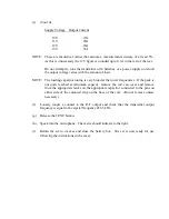
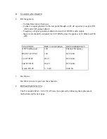
TX Stage Gain
- ALC control maximum CCW
- Key transmitter
- Measurements made with 1000 Hz audio signal input
- Transmitter tuned to average gain channel with 0.3A R.F. into 50 Ohm.
TEST POINT
VOLTAGE
REMARKS
MIC test jack TP110
4 - 6 mV RMS
This level adjusted to result in
correct voltage at AUD test
point.
AUD test jack TP109
45 mV RMS
1000 Hz Audio
IF - 2 test jack TP103
120 mV P-P
Scope measurement only
DSB minus carrier
Two Tone Pattern
Junction D108 &
Input of FL103
100 mV RMS
Junction R159 & FL 103
70 mV RMS
R159 turned max CCW
When R159 is set, the
voltage on the tap will
vary widely with frequency
e.g. 10 - 30 mV RMS
C test jack TP106
2.5 V RMS
Channel frequency. R159 turned
CCW to result in 0.3A Antenna
Current into 50 Ohms with tank
tuned.


