NGW 300 / LGW 300 / GBW 300
9 Repair
905
9.2
Disassembly and reassembly
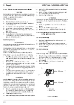
9.2.1 Replacement of the temperature limiter
General information
Before the temperature limiter is replaced, the heater
must be switched off, so that fault entries in the control
unit and thus locking of the heater is avoided.
9.2.1.1 Disassembly
1. Disconnect
the
electricity
supply to the temperature
limiter.
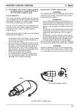
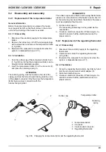
2. Remove the rubber cap. Lift off the retaining springs
with a screwdriver and remove the temperature limiter
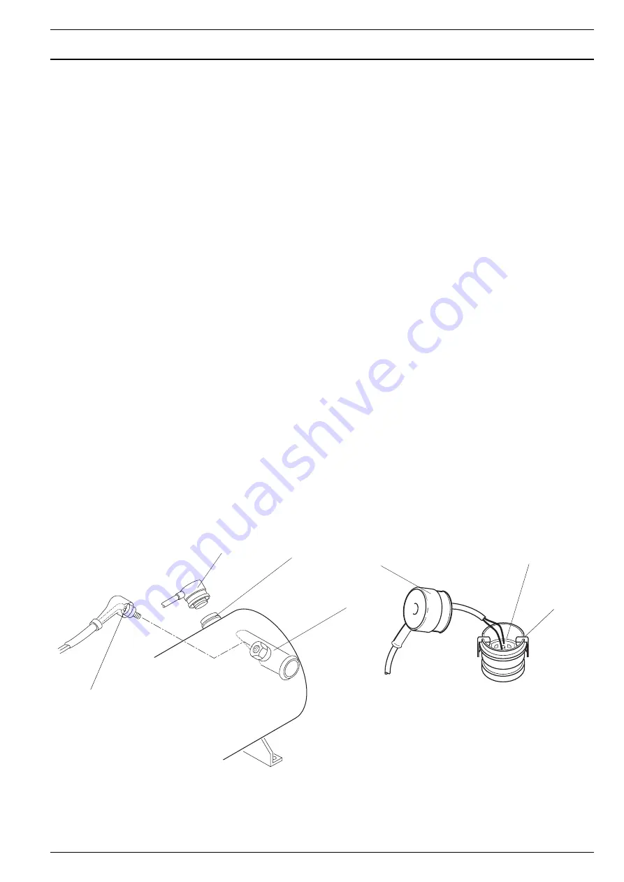
(1, fig. 904).
3. Implement the measures for components when the
system is disassembled (see 9.1.1).
9.2.1.2 Installation
1. Push the rubber cap of the temperature limiter back
(1, fig. 904) so far that the temperature limiter can be
brought into its installation position.
2. Insert the temperature limiter (1) in the connector (2)
and press the retaining spring in.
ATTENTION
The retaining spring must be located in the slot of the
casing, and must be felt and heard locking onto the union
of the adapter connector. Only then does the temperature
limiter have a proper connection with the
heat exchanger jacket.
PLEASE NOTE
The rubber cap must be fitted in such a way that its cable
sleeve runs in the direction of the heater’s centre line. Af-
ter the rubber cap has been fitted, the cable in the sleeve
must be adjusted without tension.
3. Put the rubber cap on.
The connecting cables may not be guided via the
reset button.
4. Create an electrical connection. While doing so, be
careful to ensure that the electrical wires are the
proper colours.
9.2.2 Replacement of the regulating thermostat
9.2.2.1 Disassembly
1. Disconnect the electricity supply to the regulating
thermostat.
2. Unscrew and remove the regulating thermostat
(4, fig. 904).
3. Implement the measures for components when the
system is disassembled (see 9.1.1).
9.2.2.2 Installation
1. Screw the regulating thermostat (4, fig. 904) by hand
into the screw plug coolant outlet adapter (3).
2. Slide the protective cap on.
3. Create an electrical connection. While doing so, be
careful to ensure that the electrical wires are the
proper colours.
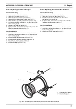
Fig. 904 Changing the temperature limiter and the regulating thermostat
1
2
3
4
1 Temperature limiter
2 Connector
3 Coolant outlet connector
4 Regulating thermostat
Rubber
Temperature
Retaining
spring
limiter
cap

