9 Repair
NGW 300 / LGW 300 / GBW 300
902
9.1.2.1 Installation of the SG 1585 control unit as a
replacement for the SG 1578 control unit
General information
The SG 1578 control unit for the NGW 300 and LGW 300
heaters is no longer available and was replaced by the
SG 1585 control unit.
The conversion kits consist of the SG 1585 control unit
and he vehicle-specific adapter wiring harness.
Conversion to the SG 1585 control must be carried out in
accordance with the following procedures.
ATTENTION
•
Replacement of the control unit must be done in an un-
energised state. Ignition must be switched off.
•
The sequence of procedures must be followed abso-
lutely so that no fault entries are made in the control
unit and conditionally upon that, as the case my be,
locking the heater is avoided.
(Fault entries are caused at the control unit by open in-
lets and outlets among other things
•
A lock on the heater can only be removed by staff who
have been trained by Spheros.
Implementation
1. Ensure that the heating system is switched off.
Where necessary, switch off the heating system by
activating the main switch, the timer or the aircondi-
tioning system and wait until it stops running.
2. Disconnect the vehicle’s and the control unit’s plugs
from the voltage supply.
3. Where necessary, disconnect the connectors between
the vehicle and the control unit and control lines.
4. Disconnect the connector to the circulating pump.
5. If required, disconnect the connector from the control
unit to the gas pressure regulator.
6. Disconnect the connector plug between the control
unit and the heater.
7. Remove the control unit and retaining spring.
8. Attach the adapter wiring harness to the new control unit.
9. Slide the new control unit with a connector to the hea-
ter downwards into the guiding groove of the burner’s
protective hood until it snaps in place in the locking
groove.
10. Attach the connector plug between the adapter wiring
harness and the heater.
11. Attach the connector plug between the adapter wiring
harness and the gas pressure regulator/solenoid.
12. Attach the connector plug between the adapter wiring
harness and the circulating pump.
13. Where necesary, attach the connector plug between the
vehicle (control line) and the adapter wiring harness.
14. Attach the connector plug between the vehicle’s
voltage supply and the adapter wiring harness.
PLEASE NOTE
•
Now, the heating system can be activated by turning
on the main switch, the timer or the airconditioning sy-
stem.
•
After all work has been completed, a trial run must be
carried out (start-up, firing operation, control pause
and after-run).
PLEASE NOTE
Conversion bags for MAN include
the SG 1585 (ID no. 9007655)
without circulation pump monitoring.
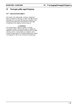
SG 1585 conversion bag for:
Standard (AMP plug)
EvoBus
MAN (AMP-plug)
MAN (Schlemmer plug)
Order no.:
90 058 91B
90 058 92B
90 077 74B
90 058 95B
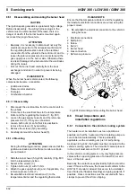
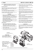
Fig. 901 Replacement of the SG 1578 control unit by the 1585 control unit
the former
SG 1578 control unit
Available conversion kits
(control unit with adapter wiring harness)
a modified
control unit SG 1585

