background image

9 Repair

NGW 300 / LGW 300 / GBW 300

908

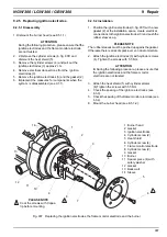
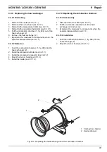
9.2.6 Replacing the flame monitor electrode

9.2.6.1 Disassembly

1.  Dismantle the burner head (see 8.5.1.1).

ATTENTION

During the following procedure, please ensure that the 
ignition electrodes and the flame monitor electrode 
are not twisted.

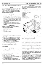
2.  Remove the cylinder screws (6, fig.. 907) and 

dismount the heat shield (5).

3. Disconnect the flame monitor electrode’s plug 

connection at the control unit and  pull back the nozzle 
(14) approx. 8 cm.

4.  Remove the screws (8) and detach the flame monitor 

electrode with the connecting line (7) approx. 7 cm.

5.  Remove the shrinking hose and disconnect the 

connecting line / flame monitor electrode plug.

6.  Implement the measures for components when the 

system  is disassembled (see 9.1.1).

9.2.6.2 Installation

1.  Attach a new gasket (9, fig. 907) to the flame monitor 

electrode¬ (7).

2.  Slide the shrinkable hose (from the replacement part 

bag) onto the flame monitor connection line and 
create a connection.

3.  Slide the shrinkable hose over the flame monitor 

electrode’s insulator (7) as far as it will go and shrink 
it so that it fits well all around and creates a seal. 

4. Attach the flame monitor electrode (7) with cylinder 

screws (8). Tighten the screws with 5,5 Nm.

5.  Attach the heat shield (5) with screws (6).

Tighten the screws with 5,5 Nm.

ATTENTION

Make sure that the ignition electrodes and the flame 
monitor electrode are not twisted.

6. Check the spacing of the ignition electrodes 

(see 6.3.3).

7. Check the spacing of the flame monitor electrode 

(see 6.3.4).

8. Lock the sleeve (14) in place in the fan casing.
9.  Mount the burner head (see 8.5.1.2).

9.2.7 Replacing the burner

9.2.7.1 Disassembly

1.  Dismantle the burner head (see 8.5.1.1).

ATTENTION

During the following procedure, please ensure that the 
ignition electrodes and the flame monitor electrode 
are not twisted.

2.  Remove the cylinder screws (6, fig.. 907) and 

dismount the heat shield (5).

3.  Unscrew and remove  spacers (11) and safety 

washers.

4.  Remove the burner(10) with the gasket (12).
5.  Implement the measures for components when the 

system  is disassembled (see 9.1.1).

9.2.7.2 Installation

1.  Bring the burner (10, fig. 907) and a new gasket (12) into 

the installation position and attach with spacers (11) and 
safety washers. Tighten the spacers with 5.5 Nm.

ATTENTION

During the following procedure, please ensure that the 
ignition electrodes and the flame monitor electrode 
are not twisted.

2.  Attach the heat shield (5) with cylinder screws (6).

Tighten the screws with 5.5 Nm anziehen.

3.  Mount the burner head (see 8.5.1.2).

9.2.8 Disassembly and reassembly of the 

burner head

9.2.8.1 Disassembly

1. Dismantle the burner head (see 8.5.1.1).
2. Dismantle the conrol unit (see 9.2.3.1).
3. Dismantle the ignition spark generator (see 9.2.4.1).
4. Disassemble the igntion electrodes (see 9.2.5.1).
5. Dismount the flame monitor electrode (see 9.2.6.1).
6. Dismount the burner (see 9.2.7.1) and remove the 

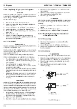
back wall (23, fig. 908) with the gasket (24).

7. Screw off the gas nozzle.
8. 4Remove 4 fillister screws and serrated washers and 

dismantle the hood.

9. Remove 2 fillister screws and serrated washers and 

loosen the bracket (2) for the wiring harness 
connector.

10. Remove the hose line to the vacuum pump (3) at the 

gas mixer.

11. Disconnect the vacuum switch (3) from the electricity 

supply.

12. Remove 2 screws, nuts and the vacuum switch (3).
13. Remove the cylinder screws (5) and dismount the 

motor (4) with the flange (6) and the gas mixer (1).

Summary of Contents for GBW 300

Page 1: ...Water heaters Workshop manual NGW 300 LGW 300 GBW 300 NGW 300 LGW 300 model 02 2006 Identification no 27 101 03B...

Page 2: ...7 Ignition spark generator with ignition electrodes 204 2 8 Vacuum switch 204 2 9 Gas inlet nozzles 204 2 10 Regulating thermostat 205 2 11 Temperature limiter 205 2 12 Circulating pump 205 2 12 1 U 4...

Page 3: ...tion solenoid in the gas intake pipe 604 7 Wiring diagrams 7 1 General information 701 8 Service work 8 1 General information 801 8 2 Work on the heater 801 8 3 Work on the vehicle 801 8 4 Trial run o...

Page 4: ...acing the SG 1585 control unit 906 9 2 4 Replacing the ignition spark generator 906 9 2 5 Replacing the ignition electrodes 907 9 2 6 Replacing the flame monitor electrode 908 9 2 7 Replacing the burn...

Page 5: ...06 System wiring for the NGW IVECO 707 707 System wiring for the LGW NGW 300 Standard and DC 708 708 System wiring for the NGW 300 EvoBus Citaro 709 709 System wiring for the NGW 300 MAN 710 801 Disas...

Page 6: ...Bureau of Motor Vehicles and Drivers for the NGW 300 LGW 300 and GBW 300 water heaters in the area governed by the StVZO Road Traffic Licensing Regulation S 291 for the NGW 300 heater S 313 for the L...

Page 7: ...instructions The year in which the heater was first put into operation must be identified by the installer on its model plate by striking out removing the inapplicable years permanently The combustion...

Page 8: ...stat in intermittent operation The heater basically consists of the burner head the heat exchanger and the combustion chamber zusammen The following components are located in the heater a control unit...

Page 9: ...s the gas pressure of the system is regulated downward from a maximum of 30 bar of excess pressure in 2 steps to barely below atmosphe ric pressure After the solenoids have opened the required quantit...

Page 10: ...eat exchanger the heat produced by combustion is transferred to the coolant circuit 2 4 Combustion chamber The gas air mixture is distributed in the combustion cham ber and is burned there The heat ex...

Page 11: ...tio nal speed of the combustion air blower The signal is processed by the control unit which then activates the so lenoids on the gas pressure regulator When there is atmospheric pressure the vacuum s...

Page 12: ...51 or the Aquavent 6000 S U 4852 circulating pump 2 12 1 The U 4851 and Aquavent 6000 S U 4852 circulating pumps The U 4851 Aquavent 6000 S U 4852 circulating pump is equipped with a brushless motor S...

Page 13: ...otor will be swit ched from error mode into the power saving sleep mode Sleep mode In sleep mode the internal users of the motor s electronic system are switched off The consumption of current in this...

Page 14: ...s extinguished but the combustion air fan and the circulating pump continue to run The circulating pump remains in operation during the control pause the operating indicator lights up If the temperatu...

Page 15: ...with an error In the error after run the fan motor is immediately shut down the circulating pump will continue to run until the end of the error after run The operating indicator light blinks If ther...

Page 16: ...ated and the heater has been examined for possible damage in particular to the cabling the temperature limiter and the regulating thermostat the head of the temperature limiter must be reset manually...

Page 17: ...3 Description of function NGW 300 LGW 300 GBW 300 304 Blank page for notes...

Page 18: ...kg h Nominal voltage 24 Volt 24 Volt Operating voltage range 21 30 Volt 21 30 Volt Rated power consumption without a circulating pump 110 W 100 W Pressure regulator used Landi Renzo TN 1 24V Landi Ren...

Page 19: ...4 Technical data NGW 300 LGW 300 GBW 300 402 Blank page for notes...

Page 20: ...al fault symptoms The following table fig 501 lists the possible general fault symptoms Fig 501 General fault symptoms page 1 of 2 Fault symptom possible cause Electrical faults The operating indicato...

Page 21: ...Flow rate in l h Heat supply kW according to model plate Temperature difference t in K or C between the water input and output measured at the heater e g with a contact thermometer x 860 Faults in th...

Page 22: ...thane content is below 95 by volume after the installation of a replacement burner PLEASE NOTE The CO2values for the NGW 300 replacement burner are set at the factory for utilisation with the delayed...

Page 23: ...re opens at 125 C 8 4 C When it cools down the temperature limiter remains open until approx 5 C Once it reaches a temperature below 90 C it can be reset by pressing the button 6 3 3 Test of the ignit...

Page 24: ...ow pressure is 2 5 0 5 mbar 6 3 8 Gas pressure regulator test ATTENTION The gas pressure regulator must not be disassembled PLEASE NOTE Testing is done when the heater is installed 6 3 8 1 General tes...

Page 25: ...o accomplish this dismount the gas hose from the gas pressure regulator and drain the oil condensate out of the gas pressure regulator and the gas hose If the gas pressure regulator s connection port...

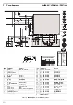
Page 26: ...0 LGW 300 GBW 300 7 Wiring diagrams 701 7 Wiring diagrams 7 1 General information Figures 701 to 709 show the system wiring diagrams of the heaters with switches and or timers and vehicle spe cific ci...

Page 27: ...ion air fan S1 ON OFF switch Heater S2 ON OFF switch Remote controlled circulating pump S3 Vacuum switch Item Designation Comment U2 Ignition electrode U3 Flame monitor electrode X1 2 pin plug connect...

Page 28: ...tion Comment U2 Ignition electrode U3 Flame monitor electrode X1 2 pin plug connection A2 control unit X2 4 pin plug connection A2 control unit X3 8 pin plug connection A2 control unit X4 4 pin plug c...

Page 29: ...k generator Item Designation Comment U2 Ignition electrode U3 Flame monitor electrode X1 2 pin plug connection A2 control unit X2 4 pin plug connection A2 control unit X3 8 pin plug connection A2 cont...

Page 30: ...Item Designation Comment U2 Ignition electrode U3 Flame monitor electrode X1 2 pin plug connection A2 control unit X2 4 pin plug connection A2 control unit X3 8 pin plug connection A2 control unit X4...

Page 31: ...U2 Ignition electrode Item Designation Comment U3 Flame monitor electrode X1 2 pin plug connection A2 control unit X2 4 pin plug connection A2 control unit X3 8 pin plug connection A2 control unit X4...

Page 32: ...t U3 Flame monitor electrode X1 2 pin plug connection A2 control unit X2 4 pin plug connection A2 control unit X3 8 pin plug connection A2 control unit X4 4 pin plug connection A2 control unit X5 4 pi...

Page 33: ...nerator Item Designation Comment X1 2 pin plug connection A2 control unit X2 4 pin plug connection A2 control unit X3 8 pin plug connection A2 control unit X4 4 pin plug connection A2 control unit X5...

Page 34: ...in plug connection A2 control unit Item Designation Comment X3 8 pin plug connection A2 control unit X4 4 pin plug connection A2 control unit X5 4 pin plug connection A2 control unit X6 2 pin plug con...

Page 35: ...esignation Comment U3 Flame monitor electrode X1 2 pin plug connector A2 control unit X2 4 pin plug connector A2 control unit X3 8 pin plug connector A2 control unit X4 4 pin plug connector A2 control...

Page 36: ...st be cleaned Outside of the heating season the heater should be operated when the vehicle s engine is cold approx every 4 weeks for 20 minutes set at warm and using the slowest fan level In that way...

Page 37: ...please ensure that the ignition electrodes and the flame monitor electrode are not twisted 1 Slide the burner head 5 fig 801 carefully 5 fig 801 into the reassembly position 2 Swivel in the screws 3...

Page 38: ...ken not to suck in any exhaust gas If the heater is installed in an enclosed installation box a ventilation opening of at least 100 cm2 is required The combustion air intake line can be extended with...

Page 39: ...eturn Gas pipe Water heating circuit wall mounted heater and roof duct heating 1 Wall mounted heater with fan 2 Heat exchanger access 3 Heater 4 Circulating pump 5 Roof heat exchanger 6 Vehicle engine...

Page 40: ...tening torque of 15 5 Nm 2 If there is an exhaust line secure it with a gripping clamp at the exhaust outlet 3 Mount the coolant hoses and secure with hose clamps 4 Open the water cocks if present 5 M...

Page 41: ...must they lead to the formation of deposits Then allow the vehicle to run at a higher speed until the cooler thermostat opens Shut down the vehicle s engine and examine the state of the coolant If ne...

Page 42: ...9 1 1 2 Visual inspection of the combustion chamber Examine the combustion chamber for scaling and re pair if necessary Examine the welded seam for cracks and repair if ne cessary PLEASE NOTE Cracks i...

Page 43: ...required disconnect the connector from the control unit to the gas pressure regulator 6 Disconnect the connector plug between the control unit and the heater 7 Remove the control unit and retaining sp...

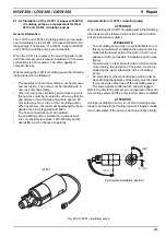
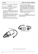
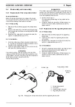
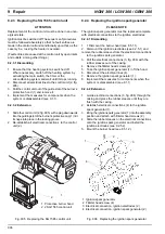
Page 44: ...s installed in a compact unit it is only possible to replace it with difficulty and its operability must be checked separately Implementation U 4851 circulating pump ATTENTION When installing the U 48...

Page 45: ...oses must be laid without kinks and going up wards Hose connections must be secured with hose clamps to prevent them from slipping No solenoids or other shut off valves which could be closed during th...

Page 46: ...proper connection with the heat exchanger jacket PLEASE NOTE The rubber cap must be fitted in such a way that its cable sleeve runs in the direction of the heater s centre line Af ter the rubber cap h...

Page 47: ...tion spark generator PLEASE NOTE The ignition spark generator must be replaced complete with electrical connections to the ignition electrodes 9 2 4 1 Dismantling 1 1 Dismount the burner head see 8 5...

Page 48: ...eeves up PLEASE NOTE The rubber sleeves must be pushed up agains the gasket Otherwise there is a risk of spark over von due to moisture 2 Attach the ignition electrodes 3 with cylinder screws 4 Tighte...

Page 49: ...2 7 Replacing the burner 9 2 7 1 Disassembly 1 Dismantle the burner head see 8 5 1 1 ATTENTION During the following procedure please ensure that the ignition electrodes and the flame monitor electrod...

Page 50: ...assembled see 9 1 1 9 2 8 2 Reassembly 1 Press the bearing 15 fig 908 onto the shaft 14 until they form a bond PLEASE NOTE Insert the pin 22 until it sticks out equally on both sides of the shaft 14 2...

Page 51: ...wo screws and nuts 19 Mount the hose line from the vacuum switch 3 to the gas mixer 1 20 Re establish the vacuum switch s 3 electrical connections 3 21 Attach the bracket 2 for the wiring harness conn...

Page 52: ...amber 1 fig 909 into the heat exchanger 2 2 Install the temperature limiter see 9 2 1 2 3 Install the temperature regulator see 9 2 2 2 4 Mount the burner head see 8 5 1 2 5 Install the heater see 8 7...

Page 53: ...with clamps ATTENTION Before installing new gas pressure regulators the enclo sed connector 1 fig 910 for the reference pressure line must be screwed into the casing cover aligned in the di rection o...

Page 54: ...ey are protected from damage during handling trasnportation and storage A description of the defect must be enclosed ATTENTION If an entire heater is being sent back it must be completely emptied When...

Page 55: ...10 Packaging Storage Shipping NGW 300 LGW 300 1002 Blank page for notes...

Reviews: