background image

13

Monitor Setup: CO2 Alarm (model 800049)

MANUAL CO2 CALIBRATION

The unit can be manually calibrated however it is not recommended
unless the unit can be kept in a known 400ppm CO2 environment for
at least

.

1

minute

• Set the instrument to be calibrated in an area where no

people, plants, or other source of CO2 is present.  The
ambient conditions should be stable.

• Connect the AC power adapter to the instrument and an

appropriate power source.

• When the reading appears, hold the

button down

TRH/M

for approximately 6 seconds->"CAL" will flash on the LCD->
"CAL

" shows->

60

meter count

release the button till “CAL60" flash,

down 1 minute.

• After

nd

d

LCD shows "E

" ,the calibration is complete .

• Re-plug the power and then on again; the meter will

return to

normal operating mode.

BACK-LIGHT FUNCTION

(98137.98139.98537.98539 models only)

When monitoring CO , Temp. RH in the dark area, long press

2

UNIT button for 5 seconds to activate back-light. Press and
hold

button again to turn off the

UNIT

function of back-light.

SETTING DATE & TIME

a)   Real time and date:

The meter shows Mo./Date and Hr/Min on the 3rd

layer of display, and each cycle is 16 seconds.

b)   Month/Date and Hour/Min

Short press

button to enter the real date and

POWER

time setting. The time default is 24-hours format.

7

8

Setting Month

M

D

Setting Year

When the number “2013"flash, press
SEL./R button to increase year(2010-
2030).Press

button to save and

TRH/M

move to next setting.

When the number “07" flash on the LCD,
press

button to increase Mo. (01-

SEL./R

12). Press

button to save and move

TRH/M

to next setting.

Though the logger shows only Month/Date, the
setting up for YEAR,too.
Enter setting up mode, edit by

or press

SEL/R

TRH/M

button to the next setting. After Month and date setting, it
displays Hour and Minute ,the same operation to set up,
always press

to save and exit.

TRH/M

H

M

H

M

Setting Date

M

D

When the number “01" flash on the LCD
, press

button to increase

SEL./R

Date (01-31). Press

button to

TRH/M

save and move to next setting.

Setting Hour

When the number “00" appear on the LCD
, press

button to increase Hr

SEL./R

(01-24). Press

button to save and

TRH/M

move to next setting.

Setting Minute

When the number “00" appear on the LCD
, press

button to increase Min.

SEL./R

(00-59). Press

button to save and

TRH/M

move to next setting.

c) Alarm setting(98536.98537.98538.98539)

After the real date and time is set, the meter will show “A-

on on the top layer of display, press

button to

SEL./R

select Alarm on or off. If alarm is on, press

button to

TRH/M

save the setting and move to Co alarm setting.

2

Press

./

SEL R

ppm

CO

2

ppm

CO

2

9

d) CO alarm level setting

2

(98536.98537.98538.98539)

The meter defaults CO 1000 ppm as the alarm value on

2

the top layer of display. To change Hi alarm value by
pressing

button to increase the value. If you

SEL./R

press

button, the number starts from Units digit,

SEL./R

Tens digit, Hundreds digit and then Thousands digit.

Press

button to save and return to CO normal

TRH/M

2

measurement.

DATALOGGING FUNCTION

If you want record the CO concentration, Temp.RH, plug with

2

supplied USB cable as below to do both on-line/off- line logging
function

(Model 9853x series only)

A

Install logger driver for Windows

.

The PL2303_Prolific_DriverInstaller_v110.exedriver is for Windows
operation system,follow the installation steps hereunder:

LOGGER SETUP

1.Put the CD into CD driver, click

PL2303_Prolific_DriverInstaller_v110.exe for installation the

driver.

2.The set up status.
3.Click “NEXT” to continue.
4.After complete the installation , press Finished

”.

B Install the logger software for Windows XP

.

Please follow the following steps to install the software
1.Put CD into CD driver , click

Setup.exe to install

10

2.Select the destination folder you are go to save by clicking

Browse button

3.Press Next

”.

4.Select “I accept the License Agreemen:(s)” and press NEXT

button.

5.Click NEXT button when you see the following.
6.Press FINISH button to complete the installation.
7.Restart the Windows XP system

C Run the software from Windows XP

.

1. Plug the USB cable into USB port, ,make sure you have already

installed the USB driver, computer will automatically detect logger ,

2. Find “Datalogger” in START

ALL PROGRAMS

3. Select logger software folder.

Software is installed completed,”Get Datalog’s Identifier”shows next
page(pic.1), then press SETTING button to enter Log setting

D. Reminder:

If logger is not plugged in USB port, the warning message “Reminder:

Data Logger is not plugged in USB port!” shows next page(pic.2) Make
sure logger is plugged in and choose the correct COM port.

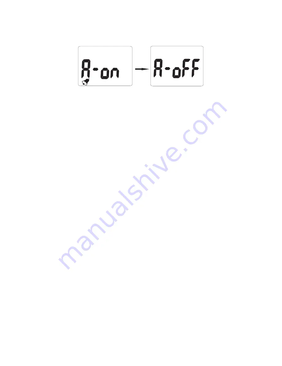
1.  After the Date and Time are set up, for model 800049, 

“A-on” appears on the display. Press SEL/R to toggle 

the alarm off and on. 

2. Press TRH/M to save the selection.

The default CO2 alarm setting is 1000 ppm.  

To change the alarm value:

1.  When “A-on” appears on the display in step 1 to indicate 

that the alarm is on, press SEL/R for 3 seconds. 

2.  Press TRH/M. The alarm value will appear on 


the display.

3.  Press SEL/R to increase the value. You may also hold 

down SEL/R as desired. The value will cycle through the 

units, tens, hundreds, and thousands digits.

4.  Press TRH/M to save the selection. The display will 

return to Normal Mode.

Summary of Contents for 800048

Page 1: ...1 IAQ Monitor Datalogging IAQ Monitor 800048 800049 Instruction Manual ...

Page 2: ...in the USA The contents of this manual may not be reproduced or transmitted in any form or by any means electronic mechanical or other means that do not yet exist or may be developed including photocopying recording or any information storage and retrieval system without the express permission from Sper Scientific ...

Page 3: ... 6 CALIBRATION 8 7 MEASUREMENT PROCEDURES 10 Minimum Maximum Readings 11 Monitor Setup 12 CO2 Alarm Setting 13 8 APPENDIX DATALOGGING 800049 15 Software Installation 16 Datalogger Settings 18 Data Sampling Recording 24 Downloading Data 26 9 TROUBLESHOOTING 29 10 POWER SUPPLY 30 11 SPECIFICATIONS 31 12 WARRANTY 32 ...

Page 4: ...C and maintenance free NDIR non dispersive infrared CO2 sensor ensure long term accuracy stability and reliability The large display continually monitors air temperature relative humidity RH and CO2 Visual alarms alert the user when CO2 exceeds customized maximum levels These instruments feature automatic baseline calibration ABC They will stand on a desk top or can be mounted on a wall An AC adap...

Page 5: ...te air quality levels Stable and accurate NDIR sensor Minimum and Maximum Readings Visual Alarms Automatic baseline calibration Desktop or wall mount capability MATERIALS SUPPLIED AC 9V 0 5A Adapter Instruction Manual USB Cable model 800049 only CD USB Driver and Logger Software model 800049 only ...

Page 6: ...6 FRONT PANEL DESCRIPTION LCD DISPLAY 1 2 3 4 5 6 7 8 9 10 11 12 ...

Page 7: ...ill notice ion CO2 pp AIR TEMP Humidity M MATERIAL SUPPLIED 1 Meter 2 Adaptor 9V 10 0 5A 98536 539 only 3 Operation manual 4 Box with color sleeve LCD DISPLAY Symbols 1 ppm CO unit 2 2 icon 350ppm 450ppm 3 icon 450ppm 700ppm 4 icon 700ppm 1000ppm 5 icon 1000ppm 2500ppm 6 icon 2500ppm 5000ppm 7 icon 5000ppm 8 Air Temp Ambient Temperature 9 DPT Dew point temperature 10 WBT Wet bulb temperature 11 MH...

Page 8: ...lly with ABC Automatic Baseline Calibration function which establishes a baseline calibration to eliminate the zero drift of the infrared sensor The ABC function is always ON when the meter is turned on ABC is designed to calibrate the meter at the minimum CO2 reading detected during 15 days continuous monitoring During power on without any disconnected DISABLE ABC FUNCTION The meter is default wi...

Page 9: ...the AC power adapter to the monitor and plug it into a power supply The unit will turn on automatically 3 Press and hold TRH M for approximately 6 seconds CAL will appear on the LCD 4 Release TRH M when CAL 60 flashes The monitor will count down 60 seconds for calibration 5 End displays on the LCD when calibration is complete 6 Unplug the adapter from the power source 7 Plug the adapter back in to...

Page 10: ...wer adapter to the monitor and plug it into a power supply 2 Set the date and time in the monitor This should be done whenever it is turned on See Monitor Setup Date and Time on p 12 for instructions 3 The monitor will warm up briefly and the reading will be displayed Levels are updated every 6 seconds 4 To change the temperature scale press UNIT to cycle the display between C and F Note When CO2 ...

Page 11: ...EL weighted average The meter keeps updating readings every minute If the meter has been powered on for less than 15 minutes the STEL value shows the weighted average of reading taken since powered on 4 n H if CALIBRATION MAINTENANCE Cleaning and storage 1 The meter should be cleaned with a damp cloth and mild detergent when necessary 2 Store the meter in an area with moderate temperature and humi...

Page 12: ...current month once set press TRH M to save the selection and move to the next setting 4 The day of the month will flash Press SEL R to select the current date once set press TRH M to save the selection and move to the next setting 5 The hour will flash Press SEL R to select the current hour once set press TRH M to save the selection and move to the next setting 6 The minutes will flash Press SEL R...

Page 13: ...e as below to do both on line off line logging function Model 9853x series only A Install logger driver for Windows The PL2303_Prolific_DriverInstaller_v110 exedriver is for Windows operation system follow the installation steps hereunder LOGGER SETUP 1 Put the CD into CD driver click PL2303_Prolific_DriverInstaller_v110 exe for installation the driver 1 After the Date and Time are set up for mode...

Page 14: ...14 ...

Page 15: ...15 Appendix Datalogging IAQ Monitor 800049 ...

Page 16: ...ct PL2303_Prolific_Driverinstaller_v110 5 Select yes to allow the program Setup exe to make changes to your computer 6 The PL 2303 Driver Installer program opens Select Next to start the installation 7 Select Finish to complete the driver installation Now you can install the logger software Installing Logger Software from Website You can now download the software that came with your meter directly...

Page 17: ...the disc 9 Double click to select Datalogger_Products Software 10 Double click again to open the folder 11 Double click to select Setup Type Application 12 Select yes to allow the program Setup exe to make changes to your computer 13 The Destination Directory appears This lists the target directories for the datalogger and software Select Next 14 Read the license agreement and select I accept the ...

Page 18: ...tware is opened If the monitor is not plugged into the correct port an error message will appear Make sure that the monitor is plugged in correctly DATALOGGER SETTINGS To Access Setting Options Select Setting from the header options on the upper left hand side of the USB Data Logger Monitor screen Comm Port and Log Setting options appear in a drop down menu Communication Comm Port Setting 1 Select...

Page 19: ...ting the Communication Port Setting If the software does not recognize that the logger is plugged into the USB port you should verify that the communications port number is correct Note The port information is found on the computer under Device Manager However depending upon your version of Windows the first steps below to access Device Manager may differ slightly 1 Open the Start Menu on the comp...

Page 20: ...or s current date and time Logger Alarm Threshold Setting Note In order to use the alarm feature during datalogging the alarm must be turned on manually before the monitor is connected to the computer using the USB cable The software will override any manually set alarm threshold and default to 1000 ppm To change the alarm threshold before datalogging Manual set COM port If software message box sh...

Page 21: ...59 Adjust the or indicators to specify the sampling rate in hours minutes and seconds 6 Adjust the or indicators to select Immediate Roll Over Schedule or Key start mode Setting Immediate Start Mode This option will cause the monitor to begin taking readings as soon as the option is confirmed Reading will continue when the monitor is detached from the USB port 1 Adjust the or indicators to specify...

Page 22: ...539 only Pic 4 Pic 3 Pic 5 D E 1 2 D Key start mode Select the mode to record once long press button press SEL R SEL R long button again to stop recording Data has to be downloaded before next key start After key off the recording the data has to download before restart the NOTE Key Start function E Roll over mode Select the mode to record when the data is full it will cover the earliest memory Af...

Page 23: ...C or F 3 The fields for the start date and time and the stop date and time will be automatically populated with default values Click on any of these fields and use the computer keyboard to make changes as desired 4 Select Ok to save the settings and exit the menu or Cancel to exit without saving the new settings Setting Key Start Mode 1 Adjust the or indicators to specify the number of sample poin...

Page 24: ...nitor Recording will continue 3 Place the monitor in the desired location for sampling 4 The datalogger will record up to 32 000 data points Once the memory is full recording will stop Sampling and Recording in Roll Over Mode 1 The green LED will flash to indicate that the monitor is recording data 2 Disconnect the USB cable from the computer and monitor Recording will continue 3 Place the monitor...

Page 25: ...te and time are reached recording will stop Sampling and Recording In Key Start Mode 1 Disconnect the USB cable from the computer and meter Place the meter in the desired location for sampling 2 At the desired start date and time press and hold the Key Start Button for 3 5 seconds The green LED will flash to indicate that the logger has started recording data 3 The datalogger will record the numbe...

Page 26: ...r computer 3 Open the Start Menu and select the Data Logger Icon from the programs list 4 The USB Data Logger Monitor screen displays 5 Click the LOGGER Status button to finish recording The datalogger ID number of records sampled and the sampling parameters and rate will display 6 Click the Download button to download the data A graph of the data will display ...

Page 27: ...n To zoom out Hold CTRL and click the right mouse button To move the graph Hold CTRL and Shift and then click and hold the left mouse button Use the cursor to move the graph To read each measurement Use the left and right arrow keys To reset the size of the graph to the default a Click on the colored bar to the left of one of the data parameters under the graph Temp Humidity Dew Point or Wet Bulb ...

Page 28: ...on The Printing Table Data dialogue box will open 3 Enter the record range you wish to print for example 1 2 350 or leave the field blank to print all the records 4 Click OK to confirm your selection 5 Click OK to start printing Saving the Data 1 Click the Save button floppy disc icon to save the data 2 Enter a unique name for the file 3 Click OK to confirm Retrieving Stored Files 1 Click the File...

Page 29: ... could cause malfunctions which require service Error Code Description E 1 CO2 sensor malfunction E 2 Humidity sensor malfunction E 3 Temperature sensor malfunction E 4 Operating temperature is too high E 5 Operating temperature is too low E 6 Hardware malfunction ...

Page 30: ...HZ Output Voltage DC 7 5 to 9 0 V Output Current 0 5 A Note Failure to use the correct power configuration will damage the monitor CE CERTIFICATE This Sper Scientific Instrument complies with EMC directive 2004 108 EC Technical standards for emissions EN 61326 1 2006 Class B EN 55011 2009 A1 2010 Group 1 Class B Immunity EN 61326 1 2006 EN 61000 4 2 2009 EN 61000 4 3 2006 A2 2010 ...

Page 31: ...10 to 50 C 0 1 C 0 6 C 10 to 50 otherwise 1 2 C 14 to 122 F 0 1 F 2 5 F RH 800048 10 to 90 0 1 5 at 25 C 10 to 99 RH otherwise 7 800049 0 1 to 99 9 CO2 0 to 9999 ppm 1 ppm 75 ppm 5 of rdg 0 to 2000 ppm Dimensions 4 4 2 108 115 51 mm Weight 6 oz 170 g ...

Page 32: ...lable This warranty does not cover probes batteries battery leakage or damage resulting from accident tampering misuse or abuse of the product Opening the meter to expose its electronics will void the warranty To obtain warranty service ship the unit postage prepaid to SPER SCIENTIFIC LTD 8281 E Evans Rd Suite 103 Scottsdale AZ 85260 The defective unit must be accompanied by a description of the p...

Reviews: