background image

26

© Titan Tool Inc.  All rights reserved.

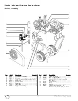
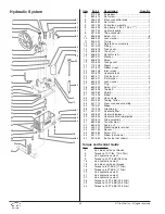
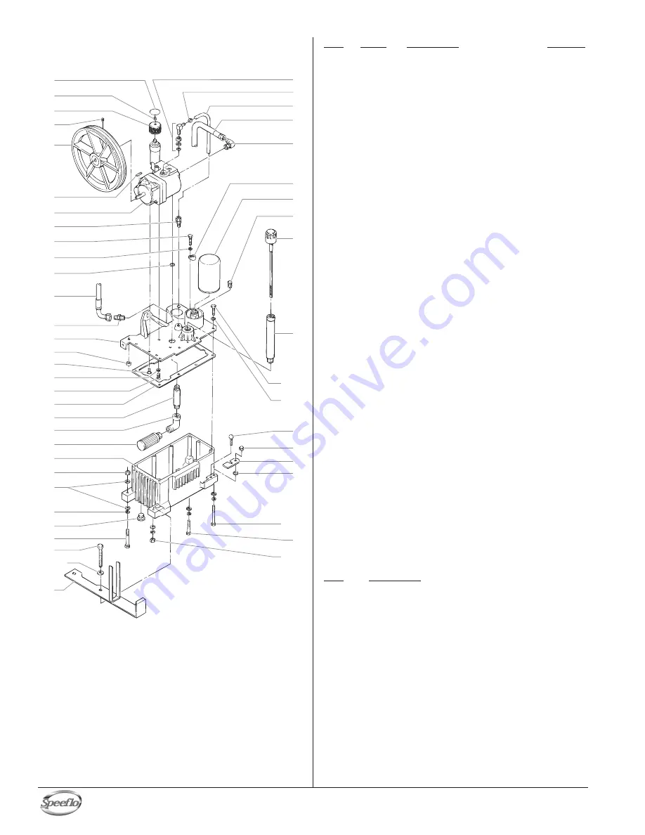
Hydraulic System

1

2

3

4

6

7

8

9

10

11

17

18

19

20

21

25

23

29

28

25

30

22

24

26

27

13

14

15
16

12

5

31

32

33

34

36

37

38

9

10

41

45

28

24

42

43
44

40

39

35

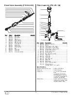
Item

Part #

Description

Quantity

1

313-755

Knob decal ...............................................1

2

862-414

Set screw..................................................1

3

448-243

Pressure control knob ..............................1

4

860-520

Set screw..................................................1

5

449-195

Pulley/fan assembly .................................1

6

448-494

Key, pump (.156 x .156 x 1

3/16

) .................1

7

449-752

Hydraulic pump ........................................1

8

431-042

Tube connector ........................................1

9

858-636

Screw, HH ................................................8

10

858-002

Lock washer ...........................................10

11

325-031

O-ring .......................................................1

12

451-115

Return hose assembly .............................1

13

451-029

Fitting........................................................1

14

449-616

Tank cover ................................................1

15

858-609

Clinch nut .................................................1

16

858-621

Socket screw ............................................2

17

859-001

Washer .....................................................2

18

858-624

Screw .......................................................2

19

449-605

Tank gasket ..............................................1

20

112-208

Nipple .......................................................1

21

472-500

Elbow, street.............................................1

22

448-208

Inlet screen...............................................1

23

449-623

Hydraulic tank...........................................1

24

862-411

Flex lock nut .............................................2

25

862-001

Flat washer...............................................6

26

862-002

Lock washer .............................................4

27

449-212

Plug ..........................................................1

28

862-493

Screw, HH ................................................2

29

862-496

Tap bolt.....................................................1

30

449-982

Shield .......................................................1

31

192-228

Elbow........................................................1

32

449-126

Hose clamp ..............................................1

33

420-250

Tubing, Teflon ...........................................1

34

451-114

Pressure hose assembly..........................1

35

192-051

Elbow........................................................1

36

101-205

Ground lug................................................1

37

451-220

Hydraulic filter...........................................1

38

449-609

Hydraulic by-pass.....................................1

39

449-626

Hydraulic fluid cap/dipstick.......................1

40

449-614

Tube assembly .........................................1

41

862-438

Thumb screw............................................1

42

862-402

Acorn nut ..................................................1

43

449-107

Mounting plate retainer ............................1

44

449-135

Spacer ......................................................1

45

862-480

Screw, HH ................................................1

46

451-121

Elbow (not shown)....................................1

47

941-555

Ball valve (not shown) ..............................1

Torque and Sealant Guide

Item

Description

4

Use blue Loctite on threads

4

Torque to 10 ft./lbs. (13.5 N/m)

8

Use hydraulic sealant

9

Torque to 20 FT/LBS (28 N/m)

13

Use hydraulic sealant

16

Use blue Loctite on threads

16

Torque to 8 FT/LBS (11 N/m)

18

Torque to 8 FT/LBS (11 N/m)

20

Use hydraulic sealant

21

Use hydraulic sealant

22

Use hydraulic sealant

28

Torque to 15 FT/LBS (20,5 N/m)

29

Torque to 15 FT/LBS (20,5 N/m)

45

Torque to 15 FT/LBS (20,5 N/m)

Summary of Contents for Gas Bare 459-350

Page 1: ...he U S A NOTE This manual contains important warnings and instructions Please read and retain for reference Model Number Gas Bare 459 350 Gas Complete 459 355 PowrTwin 12000XL T DI Do not use this equ...

Page 2: ...can be harmful if inhaled or come in contact with the body Vapors can cause severe nausea fainting or poisoning PREVENTION Use a respirator or mask if vapors can be inhaled Read all instructions suppl...

Page 3: ...ng instructions are not completely understood or if you are in doubt as to whether the product is properly grounded Do not modify the plug provided If the plug will not fit the outlet have the proper...

Page 4: ...3300 PSI 22 8 MPa Power Honda 9 HP 4 stroke single cylinder overhead valve engine w oil alert Fuel capacity 1 6 US gallons approx 2 5 hours run time Halogenated solvent compatible Yes Weight 188 lbs 8...

Page 5: ...nk cap is closed properly and securely Be careful not to spill fuel when refueling Spilled fuel or fuel vapor may ignite If any fuel is spilled make sure the area is dry before starting the engine Avo...

Page 6: ...ing or operating this sprayer 1 Make sure the bleed hose is threaded into the bleed valve It has factory installed Teflon tape on the fitting and should be tightened wrench tight 2 Attach a minimum of...

Page 7: ...ened and the motor starts without full load This reduces the amperage draw on starting and may avoid tripping the circuit breaker Preparing a New Sprayer If this sprayer is new it is shipped with test...

Page 8: ...NOTE Make sure that the spray gun does not have a tip or tip guard installed NOTE If you are spraying a water based latex flush with warm clean water If you are using any other material check with th...

Page 9: ...onal overspray Trigger lock in locked position Pressure Relief Procedure Be sure to follow the pressure relief procedure when shutting the sprayer down for any purpose including servicing or adjusting...

Page 10: ...en position Pressure Control Knob Bleed Valve 10 Titan Tool Inc All rights reserved Cleaning a Clogged Tip 1 Follow the Pressure Relief Procedure in the Operation section of this manual 2 If the tip c...

Page 11: ...ughly on the inside Soak in solvent to loosen hardened paint or replace Filter Cap Assembly Filter Element w Ball Teflon Gasket thick Teflon Gasket thin Teflon O ring Carbide Seat Filter Body Spring M...

Page 12: ...anual provided 2 To conserve fuel service life and efficiency of the sprayer always operate the gasoline engine at the lowest RPM at which it runs smoothly without laboring and delivers the amount req...

Page 13: ...ose and or reduce hose length 1 Replace packing Cause 1 Air in system 2 Dirty gun 3 Needle assembly out of adjustment 4 Broken or chipped seat 1 Worn or broken needle seat 2 Needle assembly out of adj...

Page 14: ...r start machine With pump cycling under pressure touch the hydraulic cylinder and the head to see if cylinder or head gets hotter This will help determine if piston seal is blown or piston nut is brok...

Page 15: ...ler tip orifice size Install pulsation dampener in system or drain existing one Reduce number of guns using pump Remove restrictions in system clean tip screen if filter is used 1 Replace tip 2 Increa...

Page 16: ...ures solvants insecticides ou autres peuvent tre nocifs s ils sont inhal s ou entrent en contact avec l organisme Les manations de ces produits peuvent provoquer de graves naus es vanouissements ou em...

Page 17: ...une ou l autre des bornes broche plate Le fil recouvert d un isolant vert avec ou sans rayures jaunes est le fil de mise la terre et doit tre branch sur la broche de mise la terre Si vous ne comprene...

Page 18: ...especialista en reconstrucci n de las manos PELIGRO VAPORES PELIGROSOS Las pinturas solventes insecticidas y dem s materiales pueden ser nocivos si se inhalan o toman contacto con el cuerpo Los vapore...

Page 19: ...n franjas amarillas o sin ellas es el alambre de conexi n a tierra que debe conectarse al conector de conexi n a tierra Verifique con un electricista o t cnico de servicio calificado si las instruccio...

Page 20: ...leed hose 1 7 730 334 Hose clamp 1 8 449 934 Belt guard assembly 1 Item Part Description Quantity 9 Hydraulic system 1 10 449 986 Belt V gas model 1 11 506 277 Convertokit 9 HP Honda gasoline gas mode...

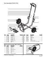
Page 21: ...451 113 Lock pin 1 12 451 112 Spring 1 13 451 059 Swing arm 1 14 856 002 Lock washer 4 15 856 921 Screw 4 16 451 053 Frame 1 17 670 109 Wheel 2 18 451 052 Plug not shown 2 19 451 455 Cart handle spac...

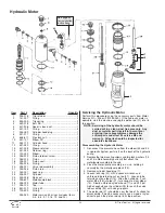
Page 22: ...he piston rod 21 into its top position Disassembling the Hydraulic Motor 1 Disconnect the pressure hose from the elbow 34 and 35 in Hydraulic System parts list on the back of the hydraulic pump 2 Remo...

Page 23: ...otor pump block 25 Be sure the open portion of the seal is facing upward V This seal requires no special tool 5 Place piston rod 21 in vise Inspect valve rod assembly 20 for any damage Make sure the l...

Page 24: ...ng 1 6 144 117 Displacement rod 1 7 138 001 Spring retainer 1 8 142 003 Lower packing spring 1 9 451 085 Outlet valve cage 1 10 138 225 Outlet valve ball 1 11 236 012 Outlet valve seat 1 12 236 032 Se...

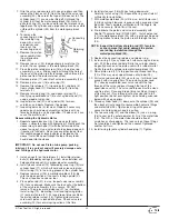
Page 25: ...00 in lbs 25 ft lbs 4 Place the wave washer 16 on top of the foot valve cage 17 5 Insert a new Teflon o ring 3 into the groove of the foot valve housing 21 Lubricate the o ring using oil or grease 6 A...

Page 26: ...5 862 001 Flat washer 6 26 862 002 Lock washer 4 27 449 212 Plug 1 28 862 493 Screw HH 2 29 862 496 Tap bolt 1 30 449 982 Shield 1 31 192 228 Elbow 1 32 449 126 Hose clamp 1 33 420 250 Tubing Teflon 1...

Page 27: ...5 7 2 DC Electric Convertokit P N 506 279 Item Part Description Quantity 1 506 259 Cover 1 2 860 501 Nut stop 4 3 860 002 Lock washer 4 4 860 004 Flat washer 8 5 860 535 Screw 2 6 978 040 Circuit brea...

Page 28: ...element 5 M w ball 1 930 006 Filter element 50 M w ball 930 007 Filter element 100 M w ball 4 920 006 Gasket Teflon thick 1 5 920 070 Gasket Teflon thin 1 6 891 193 O ring Teflon 1 7 180 909 Seat tun...

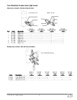
Page 29: ...555 Valve Ball 1 1 3 227 006 Nipple Hex 1 1 808 555 Nipple Hex 1 1 4 227 033 Plug Pipe 1 1 5 970 100 Block Manifold 1 1 6 814 004 Nipple Hex 1 1 Multiple Gun Add On Manifold Assemblies 975 212 975 21...

Page 30: ...Tips are selected by the orifice size and fan width The proper selection is determined by the fan width required for a specific job and by the orifice size that will supply the desired amount of fluid...

Page 31: ...Titan Tool Inc All rights reserved 31 Notes Nota...

Page 32: ...Titan sales service outlet All transportation charges including return to the factory if necessary are to be borne and prepaid by the End User Repaired or replaced equipment will be returned to the En...

Reviews: