background image

© Titan Tool Inc.  All rights reserved.

3

WARNING:  GENERAL

Can cause severe injury or property damage.

• Read all instructions and safety precautions before operating

equipment.

• Follow all appropriate local, state, and national codes

governing ventilation, fire prevention, and operation. 

• The United States Government Safety Standards have been

adopted under the Occupational Safety and Health Act
(OSHA).  These standards, particularly part 1910 of the
General Standards and part 1926 of the Construction
Standards should be consulted.

• Use only manufacturer authorized parts.  User assumes all

risks and liabilities when using parts that do not meet the
minimum specifications and safety requirements of the pump
manufacturer.

• All hoses, fittings, and filter parts must be secured before

operating spray pump.  Unsecured parts can eject at great
force or leak a high pressure fluid stream causing severe
injury.

• Before each use, check all hoses for cuts, leaks, abrasion or

bulging of cover.  Check for damage or movement of
couplings. Immediately replace the hose if any of these
conditions exist.  Never repair a paint hose. Replace it with
another grounded high-pressure hose.

• Do not kink or over-bend the hose. Airless hose can develop

leaks from wear, kinking and abuse.  A leak can inject
material into the skin.  

• Do not expose the hose to temperatures or pressures in

excess of those specified by manufacturer.

• Do not spray outdoors on windy days.
• Wear clothing to keep paint off skin and hair.
• Do not operate or spray near children.  Keep children away

from the equipment at all times.

• Do not overreach or stand on an unstable support.  Keep

effective footing and balance at all times.

• Use lowest possible pressure to flush equipment.
• Stay alert and watch what you are doing.
• Do not operate the unit when fatigued or under the influence

of drugs or alcohol.

• For electric units — Always unplug cord from outlet before

working on equipment.

• Do not use the hose as a strength member to pull or lift the

equipment.

• Do not lift by cart handle when loading or unloading.

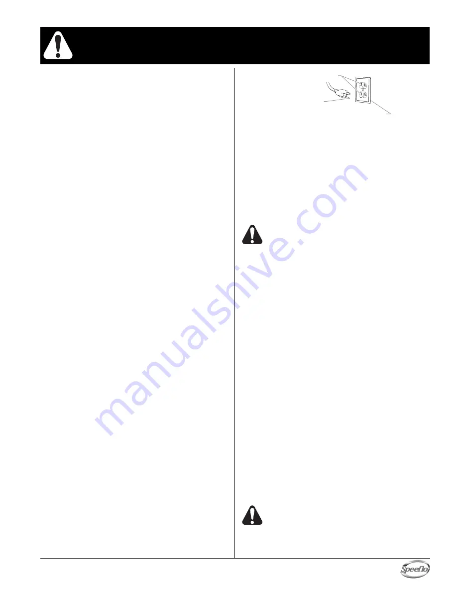
Grounding Instructions

Electric models must be grounded. In the event of an electrical
short circuit, grounding reduces the risk of electric shock by
providing an escape wire for the electric current. This product is
equipped with a cord having a grounding wire with an appropriate
grounding plug. The plug must be plugged into an outlet that is
properly installed and grounded in accordance with all local codes
and ordinances.

DANGER

— Improper installation of the grounding plug can result

in a risk of electric shock.  If repair or replacement of the cord or
plug is necessary, do not connect the green grounding wire to
either flat blade terminal. The wire with insulation having a green
outer surface with or without yellow stripes is the grounding wire
and must be connected to the grounding pin.
Check with a qualified electrician or serviceman if the grounding
instructions are not completely understood, or if you are in doubt
as to whether the product is properly grounded.  Do not modify the
plug provided.  If the plug will not fit the outlet, have the proper
outlet installed by a qualified electrician.

IMPORTANT - Use only a 3-wire extension cord that has a 3-
blade grounding plug and a 3-slot receptacle that will accept
the plug on the product.  Make sure your extension cord is in
good condition.  When using an extension cord, be sure to
use one heavy enough to carry the current your product will
draw.  An undersized cord will cause a drop in line voltage
resulting in loss of power and overheating.  A 12 gauge cord is
recommended.  If an extension cord is to be used outdoors, it
must be marked with the suffix W-A after the cord type
designation.  For example, a designation of SJTW-A would
indicate that the cord would be appropriate for outdoor use.

Gasoline Engine Safety

The engine exhaust from this unit contains chemicals
known to the State of California to cause cancer,
birth defects, or other reproductive harm.

• Honda engines are designed to give safe and dependable

service if operated according to instructions.  Read and
understand the Honda Owner's Manual before operating the
engine.  Failure to do so could result in personal injury or
equipment damage.

• To prevent fire hazards and to provide adequate ventilation,

keep the engine at least 1 meter (3 feet) away from buildings
and other equipment during operation.  Do not place
flammable objects close to the engine.

• Children and pets must be kept away from the area of

operation due to a possibility of burns from hot engine
components or injury from any equipment the engine may be
used to operate. 

• Know how to stop the engine quickly, and understand the

operation of all controls.  Never permit anyone to operate the
engine without proper instructions. 

• Gasoline is extremely flammable and is explosive under

certain conditions. 

• Refuel in a well-ventilated area with the engine stopped.  Do

not smoke or allow flames or sparks in the refueling area or
where gasoline is stored. 

• Do not overfill the fuel tank.  After refueling, make sure the

tank cap is closed properly and securely. 

• Be careful not to spill fuel when refueling.  Fuel vapor or

spilled fuel may ignite.  If any fuel is spilled, make sure the
area is dry before starting the engine. 

• Never run the engine in an enclosed or confined area.

Exhaust contains poisonous carbon monoxide gas; exposure
may cause loss of consciousness and may lead to death. 

• The muffler becomes very hot during operation and remains

hot for a while after stopping the engine.  Be careful not to
touch the muffler while it is hot.  To avoid severe burns or fire
hazards, let the engine cool before transporting it or storing it
indoors. 

• Never ship/transport unit with gasoline in the tank.

DO NOT use this equipment to spray water or acid.

IMPORTANT:  Do not lift by cart handle when loading or
unloading.

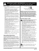
Grounded Outlet

Grounding Pin 

Cover for grounded outlet box 

IMPORTANT SAFETY INFORMATION

• 

Read all safety information

before operating the equipment.  SAVE THESE INSTRUCTIONS.

Summary of Contents for Gas Bare 459-350

Page 1: ...he U S A NOTE This manual contains important warnings and instructions Please read and retain for reference Model Number Gas Bare 459 350 Gas Complete 459 355 PowrTwin 12000XL T DI Do not use this equ...

Page 2: ...can be harmful if inhaled or come in contact with the body Vapors can cause severe nausea fainting or poisoning PREVENTION Use a respirator or mask if vapors can be inhaled Read all instructions suppl...

Page 3: ...ng instructions are not completely understood or if you are in doubt as to whether the product is properly grounded Do not modify the plug provided If the plug will not fit the outlet have the proper...

Page 4: ...3300 PSI 22 8 MPa Power Honda 9 HP 4 stroke single cylinder overhead valve engine w oil alert Fuel capacity 1 6 US gallons approx 2 5 hours run time Halogenated solvent compatible Yes Weight 188 lbs 8...

Page 5: ...nk cap is closed properly and securely Be careful not to spill fuel when refueling Spilled fuel or fuel vapor may ignite If any fuel is spilled make sure the area is dry before starting the engine Avo...

Page 6: ...ing or operating this sprayer 1 Make sure the bleed hose is threaded into the bleed valve It has factory installed Teflon tape on the fitting and should be tightened wrench tight 2 Attach a minimum of...

Page 7: ...ened and the motor starts without full load This reduces the amperage draw on starting and may avoid tripping the circuit breaker Preparing a New Sprayer If this sprayer is new it is shipped with test...

Page 8: ...NOTE Make sure that the spray gun does not have a tip or tip guard installed NOTE If you are spraying a water based latex flush with warm clean water If you are using any other material check with th...

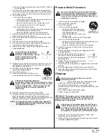
Page 9: ...onal overspray Trigger lock in locked position Pressure Relief Procedure Be sure to follow the pressure relief procedure when shutting the sprayer down for any purpose including servicing or adjusting...

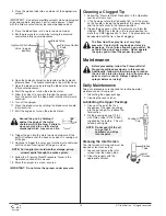
Page 10: ...en position Pressure Control Knob Bleed Valve 10 Titan Tool Inc All rights reserved Cleaning a Clogged Tip 1 Follow the Pressure Relief Procedure in the Operation section of this manual 2 If the tip c...

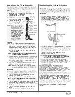
Page 11: ...ughly on the inside Soak in solvent to loosen hardened paint or replace Filter Cap Assembly Filter Element w Ball Teflon Gasket thick Teflon Gasket thin Teflon O ring Carbide Seat Filter Body Spring M...

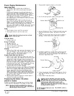
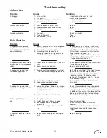
Page 12: ...anual provided 2 To conserve fuel service life and efficiency of the sprayer always operate the gasoline engine at the lowest RPM at which it runs smoothly without laboring and delivers the amount req...

Page 13: ...ose and or reduce hose length 1 Replace packing Cause 1 Air in system 2 Dirty gun 3 Needle assembly out of adjustment 4 Broken or chipped seat 1 Worn or broken needle seat 2 Needle assembly out of adj...

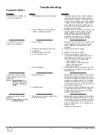
Page 14: ...r start machine With pump cycling under pressure touch the hydraulic cylinder and the head to see if cylinder or head gets hotter This will help determine if piston seal is blown or piston nut is brok...

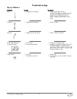
Page 15: ...ler tip orifice size Install pulsation dampener in system or drain existing one Reduce number of guns using pump Remove restrictions in system clean tip screen if filter is used 1 Replace tip 2 Increa...

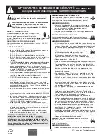
Page 16: ...ures solvants insecticides ou autres peuvent tre nocifs s ils sont inhal s ou entrent en contact avec l organisme Les manations de ces produits peuvent provoquer de graves naus es vanouissements ou em...

Page 17: ...une ou l autre des bornes broche plate Le fil recouvert d un isolant vert avec ou sans rayures jaunes est le fil de mise la terre et doit tre branch sur la broche de mise la terre Si vous ne comprene...

Page 18: ...especialista en reconstrucci n de las manos PELIGRO VAPORES PELIGROSOS Las pinturas solventes insecticidas y dem s materiales pueden ser nocivos si se inhalan o toman contacto con el cuerpo Los vapore...

Page 19: ...n franjas amarillas o sin ellas es el alambre de conexi n a tierra que debe conectarse al conector de conexi n a tierra Verifique con un electricista o t cnico de servicio calificado si las instruccio...

Page 20: ...leed hose 1 7 730 334 Hose clamp 1 8 449 934 Belt guard assembly 1 Item Part Description Quantity 9 Hydraulic system 1 10 449 986 Belt V gas model 1 11 506 277 Convertokit 9 HP Honda gasoline gas mode...

Page 21: ...451 113 Lock pin 1 12 451 112 Spring 1 13 451 059 Swing arm 1 14 856 002 Lock washer 4 15 856 921 Screw 4 16 451 053 Frame 1 17 670 109 Wheel 2 18 451 052 Plug not shown 2 19 451 455 Cart handle spac...

Page 22: ...he piston rod 21 into its top position Disassembling the Hydraulic Motor 1 Disconnect the pressure hose from the elbow 34 and 35 in Hydraulic System parts list on the back of the hydraulic pump 2 Remo...

Page 23: ...otor pump block 25 Be sure the open portion of the seal is facing upward V This seal requires no special tool 5 Place piston rod 21 in vise Inspect valve rod assembly 20 for any damage Make sure the l...

Page 24: ...ng 1 6 144 117 Displacement rod 1 7 138 001 Spring retainer 1 8 142 003 Lower packing spring 1 9 451 085 Outlet valve cage 1 10 138 225 Outlet valve ball 1 11 236 012 Outlet valve seat 1 12 236 032 Se...

Page 25: ...00 in lbs 25 ft lbs 4 Place the wave washer 16 on top of the foot valve cage 17 5 Insert a new Teflon o ring 3 into the groove of the foot valve housing 21 Lubricate the o ring using oil or grease 6 A...

Page 26: ...5 862 001 Flat washer 6 26 862 002 Lock washer 4 27 449 212 Plug 1 28 862 493 Screw HH 2 29 862 496 Tap bolt 1 30 449 982 Shield 1 31 192 228 Elbow 1 32 449 126 Hose clamp 1 33 420 250 Tubing Teflon 1...

Page 27: ...5 7 2 DC Electric Convertokit P N 506 279 Item Part Description Quantity 1 506 259 Cover 1 2 860 501 Nut stop 4 3 860 002 Lock washer 4 4 860 004 Flat washer 8 5 860 535 Screw 2 6 978 040 Circuit brea...

Page 28: ...element 5 M w ball 1 930 006 Filter element 50 M w ball 930 007 Filter element 100 M w ball 4 920 006 Gasket Teflon thick 1 5 920 070 Gasket Teflon thin 1 6 891 193 O ring Teflon 1 7 180 909 Seat tun...

Page 29: ...555 Valve Ball 1 1 3 227 006 Nipple Hex 1 1 808 555 Nipple Hex 1 1 4 227 033 Plug Pipe 1 1 5 970 100 Block Manifold 1 1 6 814 004 Nipple Hex 1 1 Multiple Gun Add On Manifold Assemblies 975 212 975 21...

Page 30: ...Tips are selected by the orifice size and fan width The proper selection is determined by the fan width required for a specific job and by the orifice size that will supply the desired amount of fluid...

Page 31: ...Titan Tool Inc All rights reserved 31 Notes Nota...

Page 32: ...Titan sales service outlet All transportation charges including return to the factory if necessary are to be borne and prepaid by the End User Repaired or replaced equipment will be returned to the En...

Reviews: