


PCI-208 / CPCI.208 manual
31.03.2004
Page 24 of 30
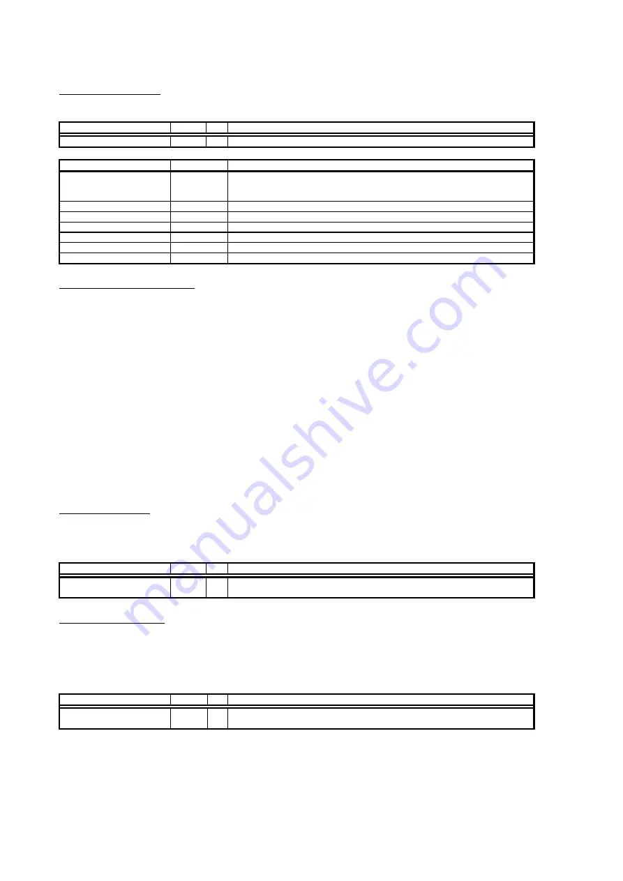
Command register
The command register executes commands like start and stop or synchronises the board with other boards.
register name
reg no.
r/w
SPC_COMMAND
0
w
command register, allowed values listed below.
status code
value
SPC_START
10
starts the board with the current register settings. If the settings of the input range has been set
since the last start of the board, the driver will hold a 200 ms delay before starting to wait the
relais settling time.
SPC_STOP
20
stops the board, data in memory is undefined.
SPC_SYNCMASTER
100
synchronisation with internal SPC100 sync bus, this board works as master
SPC_SYNCSLAVE
110
synchronisation with internal SPC100 sync bus, this board works as slave
SPC_NOSYNC
120
no synchronisation
SPC_SYNCTRIGGERMASTER
101
synchronisation: board generates trigger for all boards
SPC_SYNCTRIGGERSLAVE
111
synchronisation: board receives trigger from trigger master board.
Synchronisation (Option)
See Hardware Part of the manual for further details.
This option allows it to connect several boards from Spectrum to generate a multi-channel system. It is possible to connect several
PCI.208/CPCI.208 with each other as well as to connect the PCI.208/CPCI.208 with other Spectrum boards using the
Spc100 Sync-Bus.
One board is the clock master and generates the clock for the other (slave) boards. The clock master is defined in hardware and has the
synchronisation master bit set in the PCI features register(see above). Only one board may be the clock master. At runtime any of the
synchronised boards may be defined as a trigger master and generates trigger information for the other boards.
If the boards are synchronised, they must be programmed in the following steps:
(1)
Set all parameters for all boards except the sync information
(2)
Set the sync information for the clock-master board.
(3)
Set the sync information for all clock-slave boards.
(2)
Start all trigger-slave boards.
(3)
Start the trigger-master board.
All boards will run with the clock generated by the clock-master board. Only the trigger-master board may generate a trigger. The trigger
settings for the trigger-slave boards will be ignored.
Memory register
This register holds the number of samples, not the number of bytes. The possible values have to be doubled in the interlace mode (200
MHz).
register name
reg no.
r/w
SPC_MEMSIZE
10000
r/w memory size for recording: 32 samples up to
installed mem
/2 samples with steps of 32
samples. When using 200 MHz mode: 64 samples up to
installed mem
with steps of 64.
Posttrigger register
Sets the number of samples to be recorded AFTER the triggerevent has been found. The corresponding pretrigger is calculated by the
formula: pretrigger = memsize - posttrigger
If the posttrigger value is higher than the programmed memsize, the triggerevent is not visible.
If the option Multiple Recording is used, this register holds the segmentsize.
register name
reg no.
r/w
SPC_POSTTRIGGER
10100
r/w posttrigger value in the range 32 samples up to 256 MSamples with steps of 32. When using
200 MHz mode the value is doubled in the driver.