background image

20

SPEKTRUM DX3S USER GUIDE

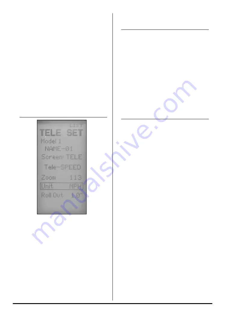
To select the telemetry sensor settings, rotate the Rolling 

Selector and place a box around Tele- SPEED then press 

the Rolling Selector. The surrounding box will flash. 

Rotate the Rolling Selector to select the desired sensor 

setting for adjustment then press the Rolling Selector.

Use the Rolling Selector to select the sensor parameters 

to adjust.

Press the Rolling Selector and a surrounding box will 

flash.

Use the Rolling Selector to adjust the value and press the 

Rolling Selector to select.

To return to the main screen press and hold the Rolling 

Selector for more than three seconds.

Tele-SPEED

Zoom - The Zoom setting sets the maximum range or 

boundary of the Speed unit. 

Unit -Select RPM, MPH, KM/H display units

Roll Out - The Roll Out function is only visible when the 

unit is set to MPH or km/h and is the internal calculator 

that allows rpm data to be converted to mph or km/h. 

When the Roll Out value is set to 1.0, the default setting, 

the value displayed on the main screen and stored in 

maximum speed, is true rpm of the shaft gear or flywheel 

that the rpm sensor is hooked up to. In order to program 

the unit to display speed in mph, a conversion factor is 

needed. Following are two methods of determining the 

conversion factor.

Method A

•  Mark the clutch bell that the sensor is reading from 

with a small reference mark. A marker works well.

•  Set the car next to a ruler and at 0” then roll the car 

forward by hand, counting each revolution of the 

reference mark. At exactly 10 revolutions stop the 

car. 

•  Measure the exact distance that the car traveled in 

ten revolutions and divide this distance by 10 (e.g. 

12.0” divided by 10 = 1.20”). 

•  Adjust the Roll Out value until 1.20 appears on the 

screen. Now all the rpm related functions will be 

displayed in mph or km/h. 

Method B

For this method you either need to know the internal gear 

ratio (normally provided in the vehicle’s manual) or be 

able to calculate the ratio via the number of teeth on the 

gears. It is also necessary to calculate the circumference 

(distance around) the tire. Once the internal ratio is 

known, and the circumference in inches has been 

determined, simply divide the circumference by the 

internal ratio and use this value as the conversion. 

To calculate circumference—multiply 3.14 x the tire’s 

diameter in inches.

To calculate internal gear ratio—divide the larger gear 

by the small gear. With multiple gear transmissions, it is 

necessary to multiply each of the larger to smaller gear 

reduction ratios to arrive at the final ratio.

Note

: The Telemetry screen displays the 

maximum recorded speed from the point 

that the receiver was turned on. To reset the 

maximum recorded speed, it is necessary to 

turn off the receiver, then back on.

www.pitstop-shop.nl

Summary of Contents for DX3S

Page 1: ... DSM Sport System with Integrated Telemetry w w w p i t s t o p s h o p n l ...

Page 2: ...mpatibility 6 Receiver Connection and Installation 7 Using the Rolling Selector 7 Main Screen 8 Telemetry Screen 9 List 10 Model Select 10 Model Name 11 Model Reset 11 Travel 12 Exponential 13 Reverse 14 Sub Trim 14 Timer 15 Bind 16 ModelMatch 16 Binding a Receiver 16 Failsafe 17 Throttle Punch 17 AUX Setting 18 Telemetry Settings 19 System 22 Installing the Telemetry Sensors in Your Vehicle 23 Ge...

Page 3: ...Battery Motor Temperature Sensor SPM1451 RPM Sensor SPM1452 Sensor Mount Hardware 21 26 SPM1501 Sensor Mount Hardware 12 15 SPM1502 Sensor Mount Hardware Electrics SPM1503 Telemetry RPM Sticker SPM1512 ModelMatch Binding The DX3S features ModelMatch patent pending ModelMatch prevents a model from being operated when the wrong model memory is selected If the wrong model memory is selected the recei...

Page 4: ...rols Antenna LCD Screen Steering Rate Knob On Off Switch Steering Trim Remote Start Button Battery Door on bottom Switch Aux Ch 2 Position Timer Button Charge Jack on back Throttle Trim Rolling Selector Steering Wheel Throttle Trigger w w w p i t s t o p s h o p n l ...

Page 5: ...ovided for convenient recharging Remove the battery door and install 4 AA batteries observing the polarity marked on the battery holder Replace the battery door Charging Charger Pigtail for Transmitter Spektrum Transmitter Charge Jack Polarity BLACK TO POSITIVE BLACK W WHITE STRIPE TO NEGATIVE A charging jack is located on the opposite side of the on off switch If rechargeable batteries are used t...

Page 6: ...atibility The DX3S features DSM technology and is also compatible with most DSM Spektrum surface receivers Compatible Spektrum Receivers The DX3S is compatible with the following DSM receivers It is not compatible with the SR3100 DSM2 receiver SR300 3 channel SPMSR300 SR3000 3 channel standard SPM1200 SR3001 3 channel Pro SPM1205 SR3500 3 channel Micro Race SPM1210 Note The SR3000HRS SPM1202 recei...

Page 7: ...unction 2 Rolling the Rolling Selector highlights function or changes settings and values when selected 3 Pressing and holding the Rolling Selector for more than 3 seconds from any screen returns the display to the Main Screen Programming is very intuitive and always starts with a press on the selector then a roll then a press then a roll and so on Most find that within a few minutes they are able...

Page 8: ... the Rolling Selector highlight the Main function and press the Rolling Selector to access the Main screen From any screen pressing and holding the Rolling Selector for more than three seconds will return the display to the main screen Note When the battery voltage drops below the preset value in the System function an alarm will sound Model Number and Name Transmitter Voltage Steering Trim Down T...

Page 9: ...ng on the operating environment To access the Telemetry screen From any screen pressing and holding the Rolling Selector for more than three seconds will first return the display to the Main screen Three seconds later the Telemetry screen will be displayed Model Number Maximum Recorded rpm Speed Transmitter Voltage Real Time rpm Speed Down Up Timer Receiver Battery Voltage Signal Strength Temperat...

Page 10: ...r and then pressing the Rolling Selector will return back to the List screen Model Select To access the Model Select function In the List screen rotate the Rolling Selector to highlight the Model Select function Press the Rolling Selector to access the Select function Rotate the Rolling Selector to highlight the Select function by placing the box around it Press the Rolling Selector and the box wi...

Page 11: ... characters is available for the model name To return to the Main screen press and hold the Rolling Selector for more than three seconds You can also use the Rolling Selector to select List Model Reset The Model Reset function is used to reset the current model memory to the factory defaults To Access the Reset Function In the List screen use the Rolling Selector to highlight the Model Reset funct...

Page 12: ...pendent travel adjustments without having to hold the wheel or trigger in the desired position To highlight both values again after moving the control in one direction simply press the Rolling Selector twice with the control centered and both values will be highlighted To return to the main screen press and hold the Rolling Selector for more than three seconds Travel The Travel screen sometimes re...

Page 13: ... the upper and lower values simultaneously If you desire to adjust the left or right Expo values independently move the corresponding channel s wheel or throttle and that value alone will be highlighted e g turning the steering wheel to the right will highlight the right value only and subsequent adjustment will affect the right travel only Note Positive and negative Expo values are available A po...

Page 14: ...nds Sub Trim The Sub Trim function is normally used to correct minor angular inaccuracies that occur when placing the servo horn on the servo In many cases the servo horn is not exactly perpendicular to the servo or in the exact optimum desired position Minor sub trim values can be used to correct this offset inaccuracy however it s important to understand that large sub trim values can limit the ...

Page 15: ...creen it is below the model number To access the Timer function From the list screen rotate the Rolling Selector to highlight the Timer function Press the Rolling Selector to enter the Timer function The Timer screen will be displayed as shown on this page Three primary timer functions are available Internal Timer Reset To reset the internal timer rotate the Rolling Selector and place the box arou...

Page 16: ...hen model 3 is selected If another model memory is selected model 5 for example the receiver will not connect If model three is again selected in the transmitter the receiver bound to model 3 will connect ModelMatch prevents operating a model using the wrong model memory Binding a Receiver 1 With the receiver off insert the bind plug into the BIND RS port SR3300T or the BIND port SR300 on the rece...

Page 17: ...the radio link is lost during use the receiver will drive the servos to their preprogrammed failsafe positions normally full brakes and straight steering If the receiver is turned on prior to turning on the transmitter the receiver will enter the fail safe mode driving the servos to their preset failsafe positions When the transmitter is turned on normal control is resumed Failsafe servo positions...

Page 18: ...ng Selector to adjust the value and direction of the auxiliary channel trim With Mix selected pressing the Rolling Selector will cause the surrounding box to flash Move the Rolling Selector to enable the mix function then press the Rolling Selector to select it With Mix Enabled the following screen will be displayed F R Disabled Forward Reverse 2 position switch disabled TrH Travel High side TrL T...

Page 19: ...only To highlight both values again after moving the wheel in one direction simply press the Rolling Selector twice with the wheel centered and both values will be highlighted To return to the main screen press and hold the Rolling Selector for more than three seconds Telemetry Settings The Telemetry setting function is used to select a default screen for display including Main Telemetry or Roll I...

Page 20: ... the clutch bell that the sensor is reading from with a small reference mark A marker works well Set the car next to a ruler and at 0 then roll the car forward by hand counting each revolution of the reference mark At exactly 10 revolutions stop the car Measure the exact distance that the car traveled in ten revolutions and divide this distance by 10 e g 12 0 divided by 10 1 20 Adjust the Roll Out...

Page 21: ...5 5 volts 4 cell 4 8 volt pack 4 4 volts Tele TEMP Unit Display Temperature Unit in degree Fahrenheit or Celsius Upper The Upper selection establishes the maximum range or boundary of the temperature scale Alert The Temperature Alert allows you to preset an alert warning when you reach a specified temperature Lower The Lower selection establishes the minimum range or boundary of the temperature sc...

Page 22: ...played on the List screen The Standard List selection enables seven commonly used functions including Model Select Model Name Travel Reverse Sub Trim Bind and System Alert The Alert sets the voltage threshold of the transmitter s battery pack at which the transmitter s alarm sounds Throttle TRIM Selects how the TH Trim switch function behaves The default function acts as a throttle trim The altern...

Page 23: ...ack voltage Note The receiver battery must be above 3 5 volts for proper telemetry operation RPM Speed Sensor Nitro An infrared sensor is provided to record rpm values that can be converted by the transmitter unit to actual speed in mph or km h The sensor emits an infrared light and a receptor records the reflection vs the absorption of light It is necessary to place a reflective or light absorbin...

Page 24: ...it section on rpm and speed for more details A mount is provided that allows the rpm sensor to be conveniently mounted in many applications Because of the diverse types of electric vehicles it may be necessary to fabricate a mount from Lexan for some types of vehicles RPM Speed Sensor Installation Electric Determine the best method to mount the sensor near the spur gear The face of the sensor must...

Page 25: ...ential hazard if not operated and maintained properly It is imperative to install your radio control system correctly Additionally your level of operating competency must be high enough to ensure you are able to control your model under all conditions If you are a newcomer to radio controlled models please seek help from an experienced modeler or your local hobby shop Safety Points to Obey for Mod...

Page 26: ...d of a truck the top of a metal work bench etc connection will take longer In some cases connection will not occur as the system is receiving reflected 2 4GHz energy from itself and is interpreting this as unfriendly noise Moving the system away from metal objects or moving the transmitter away from the receiver and powering the system up again will cause a connection to occur This only happens du...

Page 27: ...om an authorized Horizon dealer Third party transactions are not covered by this warranty Proof of purchase is required for warranty claims Further Horizon reserves the right to change or modify this warranty without notice and disclaims all other warranties express or implied b Limitations HORIZON MAKES NO WARRANTY OR REPRESENTATION EXPRESS OR IMPLIED ABOUT NON INFRINGEMENT MERCHANTABILITY OR FIT...

Page 28: ...obby com or call 877 504 0233 toll free to speak to a product support representative Inspection or Repairs If this Product needs to be inspected or repaired please call for a Return Merchandise Authorization RMA Pack the Product securely using a shipping carton Please note that original boxes may be included but are not designed to withstand the rigors of shipping without additional protection Shi...

Page 29: ... 7NS United Kingdom Please call 44 1279 641 097 or sales horizonhobby co uk with any questions or concerns regarding this product or warranty Germany Electronics and engines requiring inspection or repair should be shipped to the following address Horizon Technischer Service Otto Hahn Str 9a 25337 Elmshorn Germany Please call 49 4121 46199 66 or service horizonhobby de with any questions or concer...

Page 30: ... 2008 Horizon Hobby Inc 4105 Fieldstone Road Champaign Illinois 61822 877 504 0233 horizonhobby com 13953 w w w p i t s t o p s h o p n l ...

Reviews: