background image

SpectraPure

®

SpectraPure

®

Inc.


480.894.5437   Call us toll-free  1.800.685.2783    

2167 East Fifth St,    Tempe, Arizona   85281

20

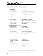
SYSTEM TROUBLESHOOTING GUIDE

1.

Low production rate:

a.

plugged prefilters.

i. Replace prefilters.

b.

low water temperature

ii. Warm feed water OR use higher GPD membrane.

c.

low line pressure.

iii. Use booster pump OR use higher GPD membrane.

d.

high TDS content.

iv. Use booster pump OR use higher GPD membrane.

e.

fouled membrane.

v. Replace membrane to restore flux.

f.

plugged flow restrictor. 

vi. Replace flow restrictor & membrane.

2.

Zero production rate:

a.

Missing flow restrictor. 

i. Install flow restrictor in the yellow line.

b.

Dried RO membrane.

ii. Try to restore flux by soaking in rubbing alcohol OR 

replace the membrane.

c.

Plugged flow restrictor.

iii. Replace flow restrictor and replace the membrane.

d.

Flush Valve is open.

iv. Close Flush Valve.

3.

Extremely high production rate:

a.

Ruptured membrane.

i. Replace membrane.

b.

Very high line pressure  

(> 80 psi). 

ii. Use a pressure regulator.

4.

Pressure gauge does not register pressure when the system is “ON”

a.

Missing flow restrictor.

i. Put flow restrictor in the yellow line.

b.

Pressure gauge screwed in 

too far.

ii. Unscrew pressure gauge one-half turn and retest.

c.

Plugged pressure gauge orifice.

iii. Clean orifice with a needle.

d.

Defective pressure gauge.

iv. Replace it.

5.

Low deionization cartridge life:

a.

Defective membrane.

i. Replace it

b.

Low pressure (< 40 psi). 

ii. Use booster pump.

c.

High CO2 levels in water  

(> 5 ppm).

iii. Aerate RO product water.

d.

High TDS in feed water  

(> 1000 ppm).

iv. NO EASY SOLUTION.

e.

Bad or faulty DI cartridge.

v. Replace DI cartridge.

f.

High pH tap water (> 9.0).

vi. Acidify feed water to the RO membrane to improve 

its rejection. 

g.

Faulty monitor/probe.

vii. Test and Replace if required.

Summary of Contents for MAXCAP RO/DI

Page 1: ...cation System Single 90 or Dual 180 Membrane Model INSTALLATION AND OPERATING MANUAL WARNING Please read carefully before proceeding with installation Failure to follow any attached instructions or operating parameter may lead to the product s failure and possible damage to property ...

Page 2: ...llation and Initialization 4 5 System Components 6 Measuring Waste to Product Water Ratio 7 Flow Restrictor Removal Adjustment and Replacement 8 9 Flow Restrictor Tables 10 Using your Systems Basic Parts Metering Diagnostics 11 Filter Diagnostics Sediment Filter Diagnostic 12 Carbon Filter Diagnostic 13 RO Membrane Diagnostic 14 18 Deionization Cartridge Diagnostic 19 Troubleshooting Guide Trouble...

Page 3: ...1880 ml min Higher TDS harder tap water higher temperature greater recovery rate or lower operating pressure may contribute to reduced permeate flow and or lower TDS rejection Reverse Osmosis Membrane Feed Water Requirements Operating Pressure 40 80 psi 2 75 5 5 bar pH Range 3 10 Maximum Temperature 113 F 45 C Maximum Turbidity 1 0 NTU Maximum Silt Density Index 5 0 based on 15 min test time Maxim...

Page 4: ...xCap DI cartridge in front of the SilicaBuster cartridge 600 gallons of water will pass through both cartridges before the MaxCap DI is exhausted The SilicaBuster DI cartridge will be only one third exhausted A second MaxCap DI will process another 600 gallons and the SilicaBuster DI cartridge will now be two thirds exhausted Only after a third MaxCap DI cartridge processes another 600 gallons wil...

Page 5: ... the back to mount the meters where ever it s convenient For example even on a wall for easier viewing 15 Open the cold water supply valve The pressure should not exceed 80 psi 16 Upon startup air may be trapped in the DI cartridges housing may not appear full this is a normal condition and it will not affect the operation of the DI system However if you later install an ASO Valve Check Valve Floa...

Page 6: ...K LINE Tap Water Input to system Supplied with garden hose adapter BLUE LINE Product Water Automate the product water with Liquid Level Controllers YELLOW LINE Concentrated Waste Water Goes to drain Use a drain saddle to connect to drain pipe DETERMINE THE VERSION OF YOUR SYSTEM Look down at the top of your system If there is a short length of red tubing attached to the yellow drain tubing then yo...

Page 7: ...uring Cup 1 Open the cold water supply valve and let the system run for 5 minutes Direct both tubes down the drain 2 Collect product water from the blue tubing into a measuring cup for one minute Measure the collected amount in milliliters 236 ml 1 cup Do the same with the waste water from the yellow tubing WASTE YELLOW IN MILLILITERS______________ DIVIDED BY PRODUCT BLUE IN MILLILITERS___________...

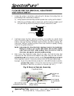
Page 8: ...he yellow tubing Fig C You may use an object such as a dull knife to help pry the flow restrictor insert from the end of the tubing The entire flow restrictor consisting of the insert collar and thin capillary tubing may then be gently extracted NOTE Sometimes the Flow Restrictor might get stuck in the membrane fitting To remove use needle nose pliers and rock the plastic collar back and forth whi...

Page 9: ...ing into the fitting until resis tance is felt approximately 1 2 inch 12 7 mm The tubing is now resting on the O ring seal inside the fitting c Firmly push the tubing approximately an additional 1 4 inch 6 35 mm further into the fitting to completely seat the line into the fitting and O ring seal 7 Turn on the system water supply and check for leaks prior to further use or testing If a leak is obs...

Page 10: ... 75 4 10 2 183 69 5 12 7 175 67 6 15 2 164 62 7 17 8 154 58 8 20 3 148 56 9 22 9 141 54 10 25 4 136 52 11 27 9 133 50 12 30 5 129 49 13 33 0 128 48 14 35 6 124 47 15 38 1 124 47 16 40 6 FR 180 GREEN PRODUCT RATE CUT TO LENGTH ml min gpd in cm 490 186 1 2 5 460 175 2 5 1 430 163 3 7 6 400 152 4 10 2 379 144 5 12 7 356 135 6 15 2 344 131 7 17 8 326 124 8 20 3 311 118 9 22 9 300 114 10 25 4 289 110 1...

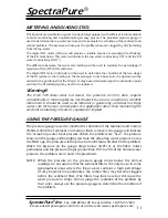
Page 11: ...f CO2 silica organic contaminants or microorganisms nor should it be used as a medical or scientific instrument It should be used as an indicator or guide only and does not imply water safe for human consumption No application other than monitoring the electrical conductivity of water is expressed or implied USING THE PRESSURE GAUGE The pressure gauge is used to monitor the condition of the Sedime...

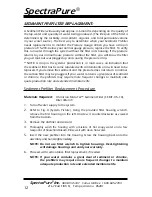
Page 12: ... remove the sediment and the pressure does not return to normal the carbon filter may be plugged If your water contains a great deal of sediment or chlorine the prefilters may require more frequent changes to maintain ade quate production rate and extended membrane life Sediment Prefilter Replacement Procedure Materials Required 0 5 micron MicroTec Sediment Filter SF MT 0 5 10 Filter Wrench 1 Turn...

Page 13: ...become saturated with contaminants but a carbon filter can also decrease production if it s covered with extremely fine sediment If the carbon becomes plugged with sediment it will no longer be able to remove chlorine Carbon Block Filter Replacement Materials Required 0 5 micron Carbon Block prefilter CF 0 5 10 Filter Wrench Chlorine Test Kit TK CL 10 KIT Procedure 1 Turn off water supply to the s...

Page 14: ... to accurately determine the condition of the RO Membrane a conductivity TDS meter capable of reading the tap water conductivity and the permeate or product water conductivity has been provided with this system With the assistance of the TDS meter you will be able to easily determine the RO membrane s condition Before performing the diagnostic test on the RO membrane make sure that the RO system h...

Page 15: ... D Divide this quantity by tap water conductivity X Y X E Rejection X Y X 100 Conductivity in the above procedure could be caused by hardness alkalinity nitrate phosphate silica etc The measurement is in ppm or mg l Rejection of the RO Membrane Calculation Example 1 Tap water hardness 150 ppm X 2 RO water hardness 7 ppm Y 3 X Y 143 ppm 4 X Y X 143 150 0 953 5 Rejection X Y X 100 0 953 100 95 3 Mem...

Page 16: ...pplied pressure The membrane is rated to produce the rated GPD at 60 psi For any pressure other than 60 psi the output GPD is multipled by the PCF PCF Line Pressure in psi 60 Calculation of Temperature Correction Factor TCF The output GPD also decreases with decrease in temperature This is because water viscosity increases with decrease in water temperature Temperature Correction Factor Table TCF ...

Page 17: ...brane housing lid This may require two people 5 Use a pair of pliers to grasp the membrane stem and pull the membrane from the housing Fig F Fig F Removing the Membrane Element black membrane brine seal black membrane housing O ring membrane product water tube 6 Remove the black housing O ring Fig F Wash the empty housing with soapy water Rinse thoroughly with hot clean water 7 Insert new membrane...

Page 18: ...and discard the flow restrictor Fig E 2 Reconnect yellow concentrate tubing back to membrane housing and run water through system for at least 2 gallons This step will flush out membrane preservatives 3 Insert the new flow restrictor and follow procedure on page 8 9 for measuring waste to product water ratio 4 Check for leaks Allow at least 2 gallons of water to run through the system before using...

Page 19: ...d hand tighten 4 Turn on system and check for leaks SILICABUSTER MAINTENANCE AND REPLACEMENT Procedure 1 When the reading on the right hand TDS meter set to OUT displays 001 it is time to replace the SilicaBuster DI cartridge 2 Make sure the DI cartridge is installed in the correct direction as marked on the cartridge shell and be sure that the top seal is securely attached to the top of the cartr...

Page 20: ...w restrictor and replace the membrane d Flush Valve is open iv Close Flush Valve 3 Extremely high production rate a Ruptured membrane i Replace membrane b Very high line pressure 80 psi ii Use a pressure regulator 4 Pressure gauge does not register pressure when the system is ON a Missing flow restrictor i Put flow restrictor in the yellow line b Pressure gauge screwed in too far ii Unscrew pressu...

Page 21: ...ch 4 Place filters back into housings and reconnect lines TIPS FOR LONG MEMBRANE LIFE 1 Replacement of 0 5 micron sediment filter once every 6 months This will prevent membrane fouling due to silt or sediment depositing on the membrane 2 Replacement of 0 5 micron carbon block filter at least once every 6 months or when chlorine breakthrough occurs This will ensure good membrane life and protect th...

Page 22: ...uld be kept in the sealed non permeable shipping bag and in a refrigerator until use The membrane can be kept there for up to 1 year DO NOT FREEZE CHOOSING A MOUNTING LOCATION When considering a location for the installation of the RO System consider the following factors Light Sources 1 Most of the components of this system are plastic and are subject to damage by ultraviolet light from the sun a...

Page 23: ...ions exceeding the feed water parameters listed in the applicable product manual refer to detailed membrane warranty information SpectraPure will on confirmation of loss of performance during the warranty period credit the prorated amount of the current catalog price of the element The disposable filters and cartridges are not covered under the warranty To obtain service under this warranty the de...

Page 24: ...tio recommended for water 180 ppm Red Flow Restrictors have a 3 1 waste ratio recommended for water 180 ppm UPGRADE PARTS Part Number Description DI MC 10HC High Capacity MaxCap DI Cartridge DI SB 10HC High Capacity SilicaBuster DI Cartridge MEM SP 0090 90 gpd SpectraSelect Plus 99 Rejection TFC Membrane Use 2 for 180 gpd systems ACCESSORIES Part Number Description MTR PH80 Hand held pH Meter TK C...

Reviews: