background image

SpectraPure

®

SpectraPure

®  

Inc.


480.894.5437   Call us toll-free  1.800.685.2783    

2167 East Fifth St,    Tempe, Arizona   85281

9

REGENERATION EVERY 
7 DAYS MINIMUM

IN SERVICE

PROGRAM

FLOW

P.M.

A- -7

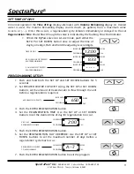
SET TIME OF DAY:                                                                                                                       

In normal operation the 

Time of Day

 display alternates with 

Volume Remaining

 display. As treated 

water is used, the Volume Remaining display counts down (in gallons) from a maximum value 
to zero or (- - -). Once this occurs, a regeneration cycle initiates immediately or delayed to the set  

Regeneration Time

. Water flow through the valve is indicated by the flashing Flow Dot Indicator.

1.  When the ByPass valve is in service mode, push either the 

SET UP or SET DOWN button once to adjust the time of 
day by one digit. Push and hold the adjust by several digits.

TIME OF DAY

IN SERVICE

PROGRAM

FLOW

P.M.

12:00

IN SERVICE

PROGRAM

FLOW

P.M.

833

IN SERVICE

PROGRAM

FLOW

P.M.

- - - -

833 GALLONS OF TREATED
WATER REMAINING

0 GALLONS OF TREATED
WATER REMAINING

PROGRAMMING SETUP:                                                                                                                       

1.  Push and hold both the SET UP and SET DOWN buttons for 5 

seconds.

2.  Set TREATED WATER CAPACITY: Using the SET UP or SET DOWN 

buttons, set the amount of treated water to flow through the unit 

before a regeneration is required.

3.  Push the EXTRA REGENERATION button.
4.  Set the REGENERATION TIME: Use the SET UP or SET DOWN 

buttons to set the desired time of day for regeneration to occur.

5.  Push the EXTRA REGENERATION button.
6.  Set the REGENERATION DAY OVERRIDE: Use the SET UP or SET 

DOWN buttons to set the maximum number of days before a 

regeneration cycle must occur.

7.  Push the EXTRA REGENERATION button to exit the program

650 GALLON CAPACITY

IN SERVICE

PROGRAM

650

FLOW

P.M.

2:00 A.M.
REGENERATION TIME

IN SERVICE

PROGRAM

FLOW

P.M.

2:00

Summary of Contents for FLEX 5600S

Page 1: ...lation Failure to follow any attached instructions or operating parameter may lead to the product s failure and possible damage to property SpectraPure Inc assumes no responsibility for water damage due to leaks It is the user s responsibility to determine that the system is leak free REV 05 26 2015 ...

Page 2: ...r hand free TABLE OF CONTENTS Thank You for your purchase of a SpectraPure System With proper installation and maintenance this system will provide you with high quality water for years to come All SpectraPure products are rigorously tested by us for safety and reliability If you have any questions or concerns please contact our customer service department at 1 800 685 2783 or refer to our online ...

Page 3: ...des Place the softener tank where you want to install the unit If you have a carbon tank you will install it in front of the water softener Both the water softener and carbon tank will need a drain line NOTE Be sure the tank s are level and on a firm base CAUTION DO NOT exceed 120 psi water pressure DO NOT exceed 110 F water temperature Keep system away from extreme hot and cold temperatures DO NO...

Page 4: ...crew the control head onto the tank DO NOT over tighten control head to tank It does not need to be airtight 4 Connect the 3 8 drain line to the Back Wash connection on the back of the control head see page 5 Con nect this line to a drain pipe 5 Turn on main water supply Open a cold water faucet in the house and let water run a few minutes or until the system is free of foreign material usually so...

Page 5: ...Tank with the inlet outlet and drain connections that meet applicable plumbing codes Perform all plumbing according to local plumbing codes Use a 1 2 minimum pipe size for the drain Use a 3 4 drain line for backwash flow rates that exceed 7 gpm or length that exceeds 20 6 m Plumbing components as shown in picture such as copper piping braided tubing and fitting do not come with the water softener ...

Page 6: ...eck to be sure that the water flows clear If necessary allow water to flow until all media fines are gone If the tap is equipped with an aerator check that is not plugged with media fines and pipe scale 7 Plug in the electrical cord and look in the sight hole on the back of the timer motor to ensure that it is running Set the days back washing to occur by sliding tabs on the skipper wheel outward ...

Page 7: ...approved power source FYI When the valve has power it will drive the Bypass Valve to the Service mode FLEX 5600SE Water Softener Head with collector screen BRINE LINE CONNECTION FROM WATER SOFTENER CONTROL HEAD INSTALLATION FOR BRINE TANK 1 Be sure that the floor under the Brine Tank is stable clean and level 2 Connect Brine Tube to compression nut fitting diag on page 8 on both the Brine Tank and...

Page 8: ...CHLORINE FREE WATER BRINE TANK CONNECTION TO DRAIN TO DRAIN BRINE DRAW TUBE BRINE TANK BRINE TANK OVERFLOW TO DRAIN FEED LINE FROM WATER SOFTENER CONTROL HEAD THROUGH HERE BRINE TANK TUBING COMPRESSION NUT COMPRESSION SLEEVE INSERT COMPRESSION FITTING DIAGRAM WATER FLOW DIAGRAM FOR CARBON TANK AND WATER SOFTENER BRINE TANK DESCRIPTION TANK CONNECTIONS ...

Page 9: ...igits TIME OF DAY IN SERVICE PROGRAM FLOW P M 12 00 IN SERVICE PROGRAM FLOW P M 833 IN SERVICE PROGRAM FLOW P M 833 GALLONS OF TREATED WATER REMAINING 0 GALLONS OF TREATED WATER REMAINING PROGRAMMING SETUP 1 Push and hold both the SET UP and SET DOWN buttons for 5 seconds 2 Set TREATED WATER CAPACITY Using the SET UP or SET DOWN buttons set the amount of treated water to flow through the unit befo...

Page 10: ...utton once to advance valve to Regeneration step 5 if active 7 Push the Extra Regeneration button once more to advance the valve back to In Service FINAL SETUP With proper valve operation verified 1 Manually step the valve to the Brine Draw position and allow the valve to draw water from the brine tank until it stops NOTE The air check will check at approximately the midpoint of the screened intak...

Page 11: ... the valve completes driving to this regeneration step position Once all regeneration steps are complete the valve returns to In Service and resumes normal operation Pushing the Extra Cycle button during a Regeneration cycle immediately advances the valve to the next cycle step position and resumes normal step timing Control Operation During Programming The control only enters the Program Mode wit...

Page 12: ...e the funnel into the softener tank as shown and slowly pour the resin into the softener tank CAUTION If you purchased a water softener that came with a bag containing gravel you must add the gravel first before the resin You will need enough gravel to completely bury the collector screen e Be careful to keep the distributor tube centered as best you can while filling Once the filling of the softe...

Page 13: ...stributor tube Do not pull upwards on the distributor tube If you do pull on the tube you will have to reposition it by blowing compressed air in the hole and pushing it back down to position g The control valve head can now be screwed back onto the carbon tank Be sure the large O ring is in place and lubricated As you start to screw the control valve onto the tank make sure the hole in the center...

Page 14: ...er Connect the Water Softener to only the hot water line This will make it possible to drink and cook with unsoftened water Install a Whole House Reverse Osmosis System Gives you full benefits of water purification technologies This method is best used with PVC piping throughout the house or an alternative RO Custom system Please call for more Information on this subject 7 What size water softener...

Page 15: ...spacers and or piston 3 Unit uses too much salt A Improper salt setting A Check salt usage and salt setting B Excess water in brine tank B See Problem 7 4 Loss of water pressure A Iron buildup in line to softener A Clean line to water conditioner B Iron buildup in water softener B Clean control and add resin cleaner to resin bed Increase frequency of regeneration C Inlet of control plugged due to ...

Page 16: ...tion C Replace seals and or piston assembly D Timer motor stopped or jammed D Replace timer GENERAL SERVICE HINTS FOR METER CONTROL if meter controller is used for water softener PROBLEM CAUSE CORRECTION 1 Softener delivers hard water A Reserve capacity has been exceeded A Check salt dosage requirements and reset program wheel to provide additional reserve B Program wheel is not rotating with mete...

Page 17: ... restricted Check that the water pressure has not dropped Increase backwash flow rate according to specifications for your unit See your dealer for recommendations 4 Loss of water pressure A Iron or turbidity buildup in water filter A Reduce days between backwashing so filter backwashes more often Make sure filter is sized large enough to handle water usage B Inlet plugged due to foreign material ...

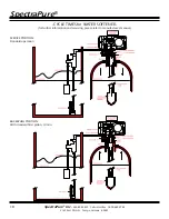
Page 18: ...free 1 800 685 2783 2167 East Fifth St Tempe Arizona 85281 18 CYCLE TIMES for WATER SOFTENER for further information and servicing please refer to manufacture s manual SERVICE POSITION Standard operation BACKWASH POSITION With standard filter piston 10 min ...

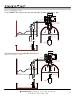
Page 19: ...0 685 2783 2167 East Fifth St Tempe Arizona 85281 19 BRINE SLOW RINSE POSITION This cycle eliminates brine solution in resin tank 60 minute pause No water flows during this time SECOND BACKWASH POSITION Double Backwash Units Only With standard filter piston 10 min ...

Page 20: ...ure Inc 480 894 5437 Call us toll free 1 800 685 2783 2167 East Fifth St Tempe Arizona 85281 20 FINAL RAPID RINSE 5 10 minutes depending on house pressure BRINE TANK REFILL POSITION 5 10 minutes depending on house pressure ...

Page 21: ...cuum damage is not covered Warranty must be presented at time of claim to the person or persons performing the repair work in order to honor warranty parts Labor Charges Labor charges incurred in connection with repair and or replacement of parts tanks or water conditioning units are expressly excluded from this warranty Transportation fees All transportation and freight costs in connection with t...

Page 22: ...__________________ Per Regeneration UNDER BEDDING ________________________________Amount _______________ MINERAL TANK SIZE Diameter ____________________Hight _________________ TYPE OF MEDIA __________________________________Cubic Feet _____________ BRINE TANK SIZE _______________________________________________ SALT SETTING PER REGENERATION _______________________________ VALVE PROGRAMMING TREATED...

Reviews: