


Spectracom Corporation
TV210V, U, G, W & TV400 V, U, G, W
TimeView Digital Display Clocks Instruction Manual
2-9
2.4.5 RS-485
Connection
The RS-485 interface connector, shown in Figure 2-4, is a removable six-position
terminal strip. The RS-485 data stream from a NetClock connects to Pins 1, 2 and 3 of
the terminal block. Connect the non-inverted RS-485 data line to Pin 1, the inverted
data line to Pin 2, and the cable shield to Pin 3. TimeView wired clocks accept Data
Formats 0 and 1 at baud rates from 1200 to 9600.
Figure 2-4: RS-485 Connection
2.4.5.1 Repeater
Output
RS-485 transmission lines should be connected in a continuous daisy chain
configuration. A branched or star configuration is not recommended, nor are long stub
lengths to the main transmission line. If these guidelines present an installation problem,
the RS-485 Repeater output can be used. The Repeater output regenerates the
synchronizing data stream applied to the RS-485 Input/Output terminal block
connections. The Repeater output can drive an additional 32 devices over cable lengths
up to 4000 feet.
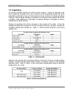
The Repeater output may be used to reduce and simplify cable runs to devices located
in different portions of the building. Figure 2-5 shows an installation in which the backup
dispatch consoles located in the basement require synchronized time.
RS-485
IN/OUT
RS-485
REPEATER


